

In spatial analysis, efficiency and precision are paramount. Geographic Information Systems (GIS) projects frequently require analysts to isolate specific geographic areas from vast, continent-wide or global datasets. Whether you are extracting county-level parcel data from a national database or isolating watershed elevation models, working with unneeded spatial data slows down processing speeds, clutter map layouts, and complicates spatial queries. This is where the ArcGIS clip tool becomes an essential component of your geoprocessing arsenal.
The ArcGIS clip tool functions as a spatial cookie cutter. It allows users to trim down point, line, or polygon vector feature classes—as well as raster datasets—using the boundary of another spatial layer. While the concept sounds simple, executing spatial clips properly requires a clear understanding of data types, coordinate reference systems, topology, and geoprocessing environment settings.
This comprehensive guide covers everything you need to know about the ArcGIS clip tool. You will learn how vector and raster clipping function, step-by-step execution methods in ArcGIS Pro, key differences between related extraction tools, automated Python scripting, and practical solutions when encountering common error messages.
Table of Contents
Understanding Spatial Clipping: Vector vs. Raster Data
To effectively clip vector data in ArcGIS or trim raster files, you must first understand how spatial data structures react to the clipping operation. The core mechanics differ significantly depending on whether your input layer consists of discrete vector geometry or continuous raster cells.
Vector Clipping Mechanics
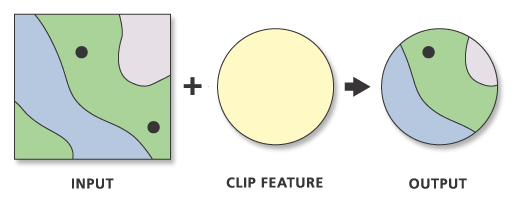
Vector clipping overlays a boundary layer—known as the clip features—onto a primary layer, referred to as the input features. The ArcGIS clip tool evaluates the geometric boundaries of the clip features and cuts through any points, polyline segments, or polygon boundaries of the input features that extend beyond that perimeter.
- Points: Points located within the clip polygon are preserved; points falling outside are deleted.
- Lines: Line segments intersecting the clip boundary are sliced at the precise intersection points. The portion inside the boundary is kept, while the exterior portion is discarded.
- Polygons: Polygon features are cropped down to the exact shape of the clip polygon. Attributes belonging to the original input feature are retained in the output attribute table.
It is important to note that vector clipping truncates geometry without altering non-spatial attribute values. For example, if a polygon representing a forest yield of 500 acres is clipped in half, the resulting attribute table will still state 500 acres unless you calculate geometry or adjust attribute rules post-clip.
Raster Clipping Mechanics
Raster data consists of a grid of cells (pixels), each containing a value representing physical observations such as elevation, rainfall, or land cover. When using the raster clip tool in ArcGIS Pro, the software performs spatial extraction based on raster geometry:
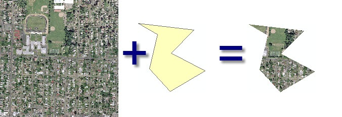
- Axis-Aligned Bounding Box: By default, clipping a raster extracts a rectangular extent bounded by the minimum and maximum X and Y coordinates (extent envelope) of the clipping layer.
- Clipping Geometry (Masking): If enabled, the tool clips the raster down to the exact irregular polygon shape of the clipping feature, assigning a
NoDatavalue to cells falling outside the polygon boundary but inside the rectangular bounding box.
Understanding these underlying mechanics ensures you select the correct tool and parameters for your specific workflow.
How to Use the Clip Tool in ArcGIS Pro (Step-by-Step)
Learning how to use clip tool in ArcGIS Pro is one of the fundamental skill sets every GIS analyst must master. Below is a detailed walkthrough for clipping vector feature classes.
Step 1: Open the Geoprocessing Pane
Launch ArcGIS Pro and open your project file containing the layers you intend to process. Navigate to the top ribbon and select the Analysis tab. Click on the Tools icon to open the Geoprocessing Pane on the right side of your screen.
Step 2: Search for the Clip Tool
In the Geoprocessing search bar, type Clip and press Enter. You will see several geoprocessing tools returned in the search results:
- Clip (Analysis Tools): Designed specifically for vector layers (points, lines, polygons).
- Clip Raster (Data Management Tools): Designed specifically for raster datasets.
For vector feature classes, select Clip (Analysis Tools).
Step 3: Configure Input and Clip Parameters
Once the tool pane opens, configure the mandatory parameters:
- Input Features: Click the drop-down menu and choose the vector layer you want to cut or reduce (e.g., nationwide highway polyline layer).
- Clip Features: Select the boundary layer that defines your area of interest (e.g., a state boundary polygon layer).
- Output Feature Class: Specify the destination geodatabase or folder path and assign a clear, descriptive file name (e.g.,
State_Highways_Clipped).
Step 4: Define Cluster Tolerance (Optional)
Under the tool’s advanced dropdown, you can set an optional Cluster Tolerance. This distance determines the minimum spacing between vertices. If vertices fall within this distance during the clipping calculation, they are snapped together. For standard projects, leaving this field blank uses the default tolerance defined by the spatial reference of the input features.
Step 5: Adjust Environment Settings
Switch to the Environments tab at the top of the Clip tool pane. Configuring proper environment settings prevents geographic displacement and missing data:
- Output Coordinate System: Set this to match your project’s local projected coordinate system to avoid spatial distortion.
- Extent: Define an explicit spatial extent if you wish to limit the processing scope further.
- Parallel Processing Factor: For massive vector datasets, entering a percentage (e.g.,
50%) utilizes multi-core CPU capabilities to drastically reduce execution time.
Step 6: Execute the Tool
Click Run at the bottom of the pane. ArcGIS Pro will execute the spatial query, output the newly clipped layer directly into your Active Map contents pane, and save the feature class to your designated geodatabase.
Clipping Raster Datasets: Methods and Tools
Clipping continuous raster surfaces requires a different approach than clipping discrete vector objects. In ArcGIS Pro, you have two primary methods for raster clipping depending on your available software licensing.
Method 1: Using the Clip Raster Tool (Data Management)
The standard tool for clipping imagery, digital elevation models (DEMs), or land cover rasters is Clip Raster, located in the Data Management toolbox.
- Search for Clip Raster in the Geoprocessing Pane.
- Set Input Raster to your raw raster file.
- Set Output Extent to your study area polygon boundary layer.
- Check the box for Use Input Features for Clipping Geometry. This crucial step ensures the raster is clipped to the exact polygon outline rather than a rectangular bounding box.
- Define the NoData Value (typically
-9999or default) to render areas outside the geometry transparent. - Select an appropriate output format (e.g., File Geodatabase Raster, Cloud Raster Format, or TIFF).
- Click Run.
Method 2: Extract by Mask (Spatial Analyst Extension)
If you possess an ArcGIS Spatial Analyst license, using the Extract by Mask tool offers superior flexibility for analytical raster extraction.
Extract by Mask extracts cell values from a raster within the spatial boundary defined by a polygon feature class or another raster layer. It automatically preserves cell alignment, spatial resolution, and pixel depth without requiring manual coordinate extent configurations. This makes it ideal for complex hydrologic modelling, topographic analyses, and satellite image classification projects.
Spatial Analysis Extraction: Clip vs. Intersect vs. Split vs. Erase
New GIS analysts often confuse clipping with other spatial extraction tools. Selecting the incorrect tool can result in corrupted datasets or inaccurate analytical conclusions. The table below illustrates the key structural differences between these common operations:
| Feature / Tool | Clip (Analysis) | Intersect (Analysis) | Split (Analysis) | Erase (Analysis) |
|---|---|---|---|---|
| Primary Function | Trims input layer to boundary extent. | Computes geometric intersection of layers. | Splits layer into multiple feature classes based on unique attributes. | Removes portions of input that overlap erase features. |
| Preserves Input Attributes? | Yes | Yes | Yes | Yes |
| Preserves Overlay Attributes? | No | Yes | No | No |
| Output Geometry | Truncated input features | Combined overlapping shapes | Multiple separate feature classes | Inverse shape of erase boundary |
| License Level Required | Basic (Desktop/Pro) | Basic (Desktop/Pro) | Basic (Desktop/Pro) | Advanced (ArcInfo) |
Clip vs Intersect: Key Differences
Understanding the difference between clip and intersect in arcgis comes down to attribute combination:
- Clip Tool: Acts purely as a spatial cookie cutter. It retains only the attribute table fields from the Input Features. None of the attribute data from the Clip Features boundary layer is added to the output file.
- Intersect Tool: Merges both geometry and tabular schema. The resulting layer contains all overlapping geometric boundaries alongside combined attribute columns from both input datasets.
If you need to know which state polygon a road falls into while trimming the road geometry, use Intersect. If you simply want to slice roads to fit inside a state boundary without altering your table schema, use Clip.
Clip vs Split
The topic of clip vs split arcgis frequently arises in multi-jurisdictional data distribution. While Clip produces a single output dataset bounded by your target geometry, Split uses a zone field (such as County_Name) within a polygon layer to divide a master dataset into dozens or hundreds of individual feature classes automatically saved into a output folder or geodatabase.
Automating the ArcGIS Clip Tool: Batch Processing & Python Scripting
When working on extensive environmental impact assessments or regional mapping projects, manually executing the clip tool dozens of times is inefficient. ArcGIS Pro provides robust options for automated batch processing.
Batch Clipping via the UI
To execute multiple clip operations simultaneously:
- Right-click the Clip tool in the Geoprocessing Pane and select Batch.
- Choose your batch parameter (e.g., Batch Input Features or Batch Clip Features).
- Fill in the dynamic parameter table or load multiple layers directly from your map contents.
- Click Run to iterate through all layers sequentially.
Automating Vector Clips with Python (ArcPy)
For maximum productivity, custom geoprocessing workflows can be scripted using Python and the arcpy site-package. Below is a robust code sample demonstrating how to iterate through a workspace of vector feature classes and clip each layer to a study area boundary:
import arcpy
import os

# Set workspace environments
arcpy.env.workspace = r"C:\GIS_Data\Input_Data.gdb"
arcpy.env.overwriteOutput = True

# Define paths for clip boundary and output destination
clip_boundary = r"C:\GIS_Data\Boundaries.gdb\Study_Area_Polygon"
output_gdb = r"C:\GIS_Data\Clipped_Output.gdb"

# Get list of all feature classes in the input geodatabase
feature_classes = arcpy.ListFeatureClasses()

print(f"Starting batch clip for {len(feature_classes)} feature classes...")

for fc in feature_classes:
    # Construct output path
    output_name = f"{fc}_Clipped"
    output_path = os.path.join(output_gdb, output_name)

    try:
        # Execute ArcPy Clip tool
        arcpy.analysis.Clip(
            in_features=fc,
            clip_features=clip_boundary,
            out_feature_class=output_path
        )
        print(f"Successfully clipped: {fc} -> {output_name}")
    except arcpy.ExecuteError:
        print(f"Error clipping {fc}:")
        print(arcpy.GetMessages(2))

print("Batch clip processing complete.")
Automating Raster Clips with ArcPy
For raster layers, call arcpy.management.Clip or use the Spatial Analyst ExtractByMask object:
import arcpy
from arcpy.sa import ExtractByMask

# Check out Spatial Analyst license
arcpy.CheckOutExtension("Spatial")

input_dem = r"C:\GIS_Data\Rasters.gdb\Regional_DEM"
mask_boundary = r"C:\GIS_Data\Boundaries.gdb\Watershed_Boundary"
output_raster_path = r"C:\GIS_Data\Rasters.gdb\Watershed_DEM_Clipped"

# Execute Extract by Mask
out_extracted_raster = ExtractByMask(input_dem, mask_boundary)

# Save the output raster
out_extracted_raster.save(output_raster_path)
print("Raster extraction complete.")
Troubleshooting Common Clip Errors
Even experienced GIS analysts occasionally encounter issues where the arcgis clip tool not working properly causes processes to fail, produce empty layers, or generate distorted outputs. Here are solutions to the most common clipping errors.
Issue 1: Empty Output Layer (0 Features Returned)
Symptom: The tool runs successfully, but the resulting output feature class contains zero records in its attribute table.
Causes & Fixes:
- Coordinate System Mismatch: If the Input Features and Clip Features use different Geographic Coordinate Systems (GCS) or Projected Coordinate Systems (PCS) without dynamic transformation, ArcGIS Pro may miscalculate their spatial intersection. Fix: Use the Project tool to reproject both layers into identical coordinate systems prior to clipping.
- Active Selections: If you have an invisible or active selection on your Clip Features boundary layer that selects an empty area, ArcGIS Pro only clips against selected features. Fix: Clear all active layer selections (
Map Tab > Clear) before running the tool. - Data Offset: The layers may visually align on screen due to fly-transformation, but their true spatial coordinates do not physically overlap. Fix: Verify feature coordinates in the layer properties pane.
Issue 2: Tool Execution Fails with “Topological Error” or Geometry Failures
Symptom: The execution halts with codes such as ERROR 000117, ERROR 000622, or geometry engine failures.
Causes & Fixes:
- Corrupted Geometries: Self-intersecting polygons, duplicate vertices, unclosed rings, or bad envelopes in either the input or clip layers cause the geometry processor to crash. Fix: Run the Repair Geometry geoprocessing tool on both input and clip layers before executing the clip.
- Complex Multipart Polygons: Polyline or polygon datasets with hundreds of thousands of vertices can exhaust system memory. Fix: Run Multipart To Singlepart to break up complex shapes, or adjust the Parallel Processing Factor environment setting.
Issue 3: Raster Clip Output is Rectangular, Not Shape-Conforming
Symptom: The raster output remains a square bounding box instead of cropping to the organic shape of your custom polygon boundary layer.
Causes & Fixes:
- Unchecked Geometry Option: When using the Clip Raster (Data Management) tool, you must explicitly check the option Use Input Features for Clipping Geometry. If left unchecked, Esri defaults to using the rectangular extent boundary envelope.
Best Practices for Optimal Spatial Extraction Workflows
To ensure maximum data integrity, speed, and efficiency when performing spatial extraction, incorporate these GIS industry standards into your organizational workflows:
- Standardize Projection Systems: Always perform geoprocessing on layers that share an identical, local Projected Coordinate System (e.g., State Plane or UTM) rather than unprojected geographic systems (e.g., WGS 1984). This ensures accurate geometric calculations and prevents snapping distortions.
- Clean Spatial Data First: Run geometry checks (
Check Geometryfollowed byRepair Geometry) on raw public domain vector files before running heavy batch extraction jobs. - Maintain Schema Consistency: Remember that clipping vector layers does not dynamically recalculate area, perimeter, or length fields in the attribute table. Always run Calculate Geometry Attributes on clipped polygon and polyline layers to update spatial measurements.
- Optimize File Storage: Avoid outputting large spatial clips to legacy ESRI Shapefiles (
.shp), which suffer from 2GB file size limits and truncated field names. Instead, store outputs inside File Geodatabases (.gdb) or Enterprise Geodatabases. - Leverage Memory Workspaces: When scripting complex workflow chains where clip outputs are merely intermediate steps, save temporary outputs to the
memoryorin_memoryworkspace (in_memory/temp_clipped) to eliminate unnecessary disk read/write cycles.
Conclusion
The ArcGIS clip tool remains one of the foundational building blocks of spatial analysis and GIS data management. Whether you are managing vector layers using standard clipping methods, extracting continuous rasters using mask layers, or automating large-scale enterprise workflows via ArcPy scripts, understanding the underlying mechanisms of spatial extraction ensures your projects remain fast, accurate, and reliable.
By following the step-by-step procedures, environment configurations, and troubleshooting methods outlined in this guide, you can eliminate data errors, streamline spatial geoprocessing pipelines, and ensure your GIS outputs meet highest technical standards.