
Welcome to the definitive guide on the Fusion 360 section view. Whether you’re a seasoned mechanical engineer, an industrial designer, or a hobbyist just starting your CAD journey, understanding how to effectively dissect your 3D models is a non-negotiable skill. It’s the digital equivalent of an X-ray, allowing you to peer inside complex assemblies, verify critical clearances, and communicate your design intent with absolute clarity.
Many users know the section view exists, but few leverage its full power. They create a simple cut and move on, missing out on advanced techniques and powerful analytical capabilities. This guide changes that. We’ll go beyond a basic cross-section view and explore everything from creating complex offset sections to troubleshooting common issues and exporting your views for professional-grade drawings. Prepare to transform your 3D model inspection workflow from a simple task into a strategic advantage.
Table of Contents
What is a Section View in CAD and Why is it Essential?
Before we dive into the specifics of Fusion 360, it’s crucial to grasp the fundamental concept. A section view, at its core, is a visualization technique that reveals the internal geometry of a 3D model. Imagine taking a physical prototype and slicing it with a perfectly flat, infinitely thin saw. The exposed face you see is the section view. In the world of CAD, this process is non-destructive and infinitely flexible.
The Core Concept of Slicing a 3D Model
The process involves defining a ‘cutting plane’ that passes through your model. The software then hides all geometry on one side of that plane, giving you an unobstructed view of the internal features. This is fundamental to a process often called CAD sectioning. It allows designers and engineers to:
- Visualize Internal Structures: See how internal components fit together without hiding or making parts transparent.
- Analyze Material Thickness: Quickly verify if walls are too thin or too thick in critical areas.
- Check for Interferences: Identify where parts might be clashing inside an assembly.
- Understand Complex Mechanisms: Observe the interaction of gears, levers, and other moving parts within their housing.
Benefits in Design, Engineering, and Manufacturing
The importance of the section view extends across the entire product development lifecycle. It’s not just a design tool; it’s a communication and validation powerhouse.
- For Designers: It helps in refining ergonomics and ensuring all internal components are packaged efficiently.
- For Engineers: It’s a critical 3D model inspection tool for performing tolerance analysis, checking clearances, and ensuring structural integrity. It’s a cornerstone of Design for Manufacturing and Assembly (DFMA).
- For Manufacturing: Section views in technical drawings, which often follow standards like those from the American Society of Mechanical Engineers (ASME), provide clear instructions for machinists and assembly technicians, reducing ambiguity and costly errors.
The Ultimate Guide to Creating a Section View in Fusion 360
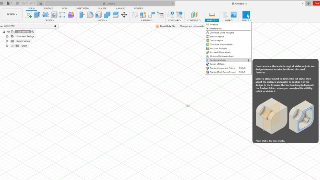
Now, let’s get practical. Fusion 360’s Section Analysis tool is located within the ‘Inspect’ dropdown menu in the Design workspace. It’s an intuitive yet powerful feature. Here’s how you can master it.
Accessing the Section Analysis Tool
- Make sure you are in the ‘Design’ workspace.
- Navigate to the main toolbar at the top of the screen.
- Click on the ‘Inspect’ tab.
- In the dropdown menu, select ‘Section Analysis’. The icon looks like a circle with a quarter section cut out.
Step-by-Step Walkthrough: Your First Cross-Section View
Let’s walk through the process of creating a standard planar section view. This is the most common type and the foundation for more advanced techniques.
- Activate the Tool: As described above, select ‘Section Analysis’ from the ‘Inspect’ menu.
- Select a Planar Face or Origin Plane: The tool will prompt you to select a face or plane to define the cut. You can either click on a flat face of your model or choose one of the origin planes (XY, XZ, YZ) from the browser tree on the left.
- Position the Cutting Plane: Once you select a plane, a manipulator gizmo will appear. It consists of arrows and rotation handles.
- Drag the Arrow: Click and drag the linear arrow to move the cutting plane through your model. You can see the section update in real-time, which is incredibly useful for finding the exact spot you want to inspect.
- Enter an Exact Distance: For precision, you can type a specific offset distance in the dialog box.
- Adjust the Angle (Optional): Use the rotational handles on the gizmo to angle the cutting plane. This is useful for slicing through features that aren’t aligned with the main axes.
- Confirm the Analysis: Once you are satisfied with the position of your section view, click ‘OK’ in the Section Analysis dialog box.
Your section view is now active. You’ll also notice a new ‘Analysis’ folder has appeared in your browser tree, containing ‘Section1’. You can toggle the visibility of this section view by clicking the eye icon next to it.
Understanding the Section Analysis Dialog Box Options
The dialog box provides several options to refine your cross-section view:
- Distance: Manually input the offset distance of the cutting plane from your selected face/plane.
- Angle X, Y, Z: Manually input rotation angles for the cutting plane around the respective axes.
- Flip: This reverses the direction of the cut, showing you the other half of the model. It’s a quick way to switch perspectives without recreating the view.
- Color: By default, the section cut is shown in the model’s material color. You can check this box to assign a specific color to the capped section faces, which can improve visibility.
- Hatching: When enabled, this applies a cross-hatching pattern to the cut faces, which is standard practice in technical drawings to denote a sectioned area.
- Section by Component: This option is incredibly powerful in assemblies. When checked, it ensures that only the selected components are sectioned, while others remain whole. This is perfect for seeing how a bolt fits into a threaded hole without cutting the bolt itself.
Advanced Section View Techniques for Power Users
Creating a simple cut is easy. But the real power of the Fusion 360 analysis tools comes from applying more advanced methods to reveal precisely the information you need.
Creating Offset and Jogged Section Views
Sometimes, a single flat plane can’t show all the features you need to see. For this, you would traditionally create an offset or jogged section in a 2D drawing. While Fusion 360 doesn’t have a dedicated ‘Jogged Section’ tool in the 3D environment, you can achieve a similar result for analysis using a combination of component visibility and multiple section analyses. However, the true power of offset sections is realized when you export a Fusion 360 section view to a drawing, a process we’ll cover later.
Using Construction Planes for Complex Angles
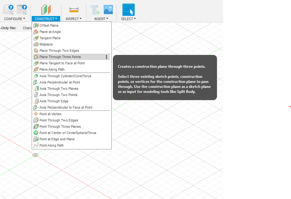
What if the feature you want to inspect lies on a complex, non-orthogonal angle? The solution is to use construction planes.
- Go to the ‘Construct’ dropdown menu.
- Create a new construction plane that aligns with the feature you want to cut through. You can use options like ‘Plane Through Three Points’ or ‘Plane Tangent to Face at Point’.
- Once your custom construction plane is created, initiate the ‘Section Analysis’ tool.
- Instead of selecting an origin plane or a model face, select your newly created construction plane as the cutting entity.
This method gives you complete control to slice your model in any orientation imaginable, which is essential for analyzing complex castings, molded parts, or intricate assemblies.
Analyzing Multiple Components in an Assembly
Working with an assembly introduces new layers of complexity and power to the section view tool. Here are some key considerations:
- Isolate and Section: Right-click a component in the browser and select ‘Isolate’. Now, when you create a section view, it will only apply to that component. Right-click and choose ‘Unisolate’ to return to the full assembly view.
- Targeted Sectioning: As mentioned earlier, use the ‘Section by Component’ option in the dialog box. This lets you create a section view that cuts through a housing but leaves the internal components like screws, bearings, and shafts intact. This is invaluable for checking alignments and clearances.
- Multiple Analyses: You can have multiple section analyses saved in your ‘Analysis’ folder. For example, you could have ‘Section1’ for a horizontal cut and ‘Section2’ for a vertical cut. You can only have one active at a time, but you can easily switch between them by toggling their visibility, which is much faster than recreating them each time.
Troubleshooting Common “Fusion 360 Section View Not Working” Issues
Even the best tools can sometimes present challenges. If you’re struggling with the section view, here are some common problems and their solutions.
Why is My Section View Greyed Out or Unavailable?
This is the most common issue. The ‘Section Analysis’ tool might be greyed out for a few reasons:
- You’re in the Wrong Workspace: The tool is primarily available in the ‘Design’ workspace. If you are in ‘Generative Design’, ‘Simulation’, ‘Manufacture’, or ‘Drawing’, the tool will be unavailable in the 3D modeling context.
- No Active Body/Component: If your design is empty or all bodies are hidden, there is nothing to analyze, and the option may be disabled.
- A Command is Active: Fusion 360’s workflow is sequential. If you are in the middle of another command (e.g., creating a sketch or an extrude), you must finish or cancel it before you can start a new one like Section Analysis.
Graphics Card and Driver Considerations
Visual glitches, such as the section cut not appearing correctly or causing graphical artifacts, are often linked to your computer’s graphics hardware. According to expert sources in 3D modeling, a powerful GPU is essential for smooth CAD operation.
- Update Your Drivers: Ensure your graphics card drivers are up to date. Visit the manufacturer’s website (NVIDIA, AMD, or Intel) to download the latest version.
- Check Fusion 360’s Graphics Diagnostics: Go to Help > Graphics Diagnostic. This tool can help you identify any issues and allows you to switch between different graphics drivers (e.g., DirectX 9, DirectX 11, OpenGL) which can sometimes resolve rendering problems.
Resetting the View and Toggling Analysis Visibility
Sometimes the simplest solution works best.
- Toggle Visibility: Go to the ‘Analysis’ folder in the browser tree. Click the eye icon next to your section view off and then on again. This can sometimes force a refresh that fixes visual bugs.
- Home View: Click the ‘Home’ icon next to the ViewCube. Resetting the camera can sometimes clear up rendering issues.
- Recreate the View: If a specific analysis view is consistently causing problems, delete it from the browser tree (right-click > Delete) and create a new one.
Beyond the Model: Using Section Views in Drawings and Presentations
A section view’s utility doesn’t end in the Design workspace. Its primary purpose in traditional engineering is for creating clear, unambiguous 2D technical drawings.
How to Export Fusion 360 Section View to a Drawing
This is a critical long-tail keyword and a vital skill. Here’s the standard workflow:
- Save your design.
- Go to the ‘File’ menu, then navigate to ‘New Drawing’ > ‘From Design’.
- In the ‘Create Drawing’ dialog, set your desired standard (e.g., ASME or ISO) and sheet size. Click OK.
- A new ‘Drawing’ workspace will open. Place your base view (e.g., a front view) of the model or assembly onto the sheet.
- From the Drawing toolbar, select ‘Section View’.
- Select the parent view you just placed.
- Now, you’ll draw a cutting line. Click to define the start point of your line, move your cursor across the parent view, and click again to define the end point. You can create multiple points to create an offset (jogged) section line.
- Press Enter to confirm the cutting line.
- Move your cursor to position the resulting section view on your sheet and click to place it.
Fusion 360 will automatically generate the correct cross-hatching and place the view with the appropriate labels, saving you an immense amount of time.
Best Practices for Communicating Design Intent
- Choose the Right View: Don’t section a part unless it reveals important information that can’t be seen from the outside.
- Clarity is Key: Ensure your cutting line is clearly defined and doesn’t pass through ambiguous geometry.
- Don’t Section Standard Parts: In assemblies, it’s standard practice not to section items like fasteners (screws, nuts, bolts), bearings, and shafts when the cutting plane runs along their axis. Fusion’s drawing tools often handle this automatically.
Leveraging Section Analysis for Deeper Insights
Think of the section view as more than just a visualization tool; it’s an analytical one. You can gain profound insights into your design’s performance and manufacturability without ever leaving the 3D environment.
- Checking Wall Thickness: After creating a section, use the ‘Inspect’ > ‘Measure’ tool to click on two opposing inner and outer walls to get an exact thickness measurement.
- Visualizing Internal Passages: For designs involving fluid dynamics, like manifolds or pump housings, a cross-section view is the only way to effectively visualize the entire fluid path to check for smooth transitions and potential restrictions.
- Combining with Other Tools: The section view is even more powerful when used in concert with other analysis features. Activate a section view, then run the ‘Interference’ tool (also under the ‘Inspect’ menu). This will check for clashes only within the visible, sectioned geometry, allowing you to pinpoint the exact location of a problem in a dense assembly.
For more detailed information on the tool itself, the official Autodesk Knowledge Network is an excellent resource for a quick feature overview.
Conclusion: The Unseen Power of a Clear View
The Fusion 360 section view is one of the most fundamental and versatile tools in your CAD arsenal. We’ve journeyed from the basic principles of CAD sectioning to the practical steps of creating your first cut. We’ve explored advanced techniques using construction planes and component-level control, tackled common troubleshooting scenarios, and bridged the gap between 3D analysis and 2D documentation.
By mastering the Section Analysis tool, you elevate your work from simply creating shapes to truly understanding the intricate relationships within your designs. You can diagnose problems faster, communicate ideas more effectively, and ultimately, engineer better products. So, open up your latest project, activate the Section Analysis tool, and start exploring the unseen world inside your own creations.