
In the world of 3D modeling and digital fabrication, symmetry is more than just an aesthetic choice; it’s a fundamental principle of engineering, efficiency, and elegance. From the balanced wings of an aircraft to the perfectly matched halves of a consumer product casing, symmetrical design is everywhere. For users of Autodesk Fusion 360, mastering the art of symmetry is not just possible—it’s streamlined, thanks to one of the most powerful tools in its arsenal: the Mirror command. This article is your ultimate guide to mastering the fusion 360 mirror body command, a skill that will fundamentally improve your design workflow, save you countless hours, and elevate the precision of your models.
Whether you’re a hobbyist 3D printing enthusiast, a mechanical engineering student, or a seasoned product designer, you’ve likely faced the challenge of creating identical, mirrored features on a part. Manually modeling both sides is not only tedious but also prone to human error. This is where the Mirror command transforms your process. We will dive deep into not just how to use the tool, but why and when to use its different variations—mirroring bodies, components, features, and faces. Get ready to unlock a more efficient and powerful way of thinking about and executing your designs in Fusion 360.
Table of Contents
Understanding the Core Concept: What is the Mirror Command in Fusion 360?
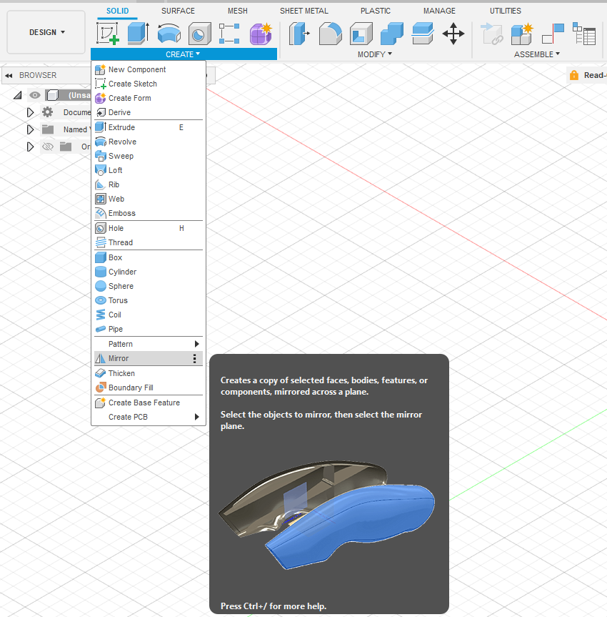
At its core, the Mirror command in Fusion 360 is a generative tool that creates a reversed copy of selected objects across a specified plane. However, to think of it as a simple “copy and flip” function is to underestimate its power. The true strength of the Mirror tool lies in its integration with Fusion 360’s parametric modeling engine.
When you mirror an object, you are not just creating a static duplicate. You are establishing a parent-child relationship between the original object (the parent) and the mirrored copy (the child). This means any changes you make to the parent geometry will automatically and instantly be reflected in the mirrored version. This parametric link is the cornerstone of efficient design iteration and ensures perfect symmetry is maintained throughout the project’s lifecycle.
Key benefits of using the Mirror command:
- Time Savings: Model only half of a symmetrical object and let Fusion 360 create the other half for you. This effectively cuts your modeling time for symmetrical parts in half.
- Guaranteed Accuracy: Manual modeling of two halves can introduce minute inconsistencies. Mirroring eliminates this risk, ensuring perfect mathematical symmetry.
- Simplified Modifications: Need to adjust a feature? Change the original, and the mirrored copy updates automatically. This is invaluable during the prototyping and refinement phases.
- Reduced Complexity: A design timeline focused on half a model is cleaner, easier to navigate, and less prone to errors or performance slowdowns.
The Anatomy of the Mirror Tool: Bodies, Components, Features, and Faces
The Mirror command is versatile, allowing you to mirror different types of objects within your design. Understanding the distinction between these is crucial for applying the tool correctly and building robust models. The dialog box for the Mirror command asks you to select a “Pattern Type,” and your choice here dictates the entire operation.
Mirroring Bodies: The Foundation
A “Body” in Fusion 360 is any single, continuous 3D shape. Think of it as a solid lump of digital material. The fusion 360 mirror body operation is the most common and fundamental use of the tool.
- When to use it: This is your go-to method when you are working on a single, monolithic part that is not yet part of a larger assembly. Examples include a symmetrical bracket, a vase, or the main housing of a device. You are focused on the geometry of one part, not its relationship with others.
Mirroring Components: For Assemblies and Motion
A “Component” is a more advanced container than a body. A component has its own origin, can contain one or more bodies, and can have joints and motion applied to it. Components are the building blocks of assemblies.
- When to use it: You must use the fusion 360 mirror component option when dealing with assemblies. If you need a distinct left-hand and right-hand version of a part (e.g., a left car door and a right car door), mirroring the component is essential. This creates a new, separate component in your browser tree that can be independently moved, assigned a unique part number in a Bill of Materials (BOM), and used in mechanical joints.
Mirroring Features: Granular Control
Sometimes, you don’t want to mirror an entire body, but just a specific operation you performed on it. This is where mirroring features comes in. Features are the individual operations in your design timeline, such as extrusions, fillets, holes, or chamfers.
- When to use it: Use the mirror feature in fusion 360 when you want to replicate a specific detail on an already existing body. For example, if you have a solid block and you add a complex pattern of holes on one side, you can simply mirror those hole features to the other side without affecting the base block.
Mirroring Faces: A Specialized Technique
This is a less common but powerful option within the surface modeling environment. It allows you to mirror individual faces of a body or surface, which can be useful for complex surface patching and sculpting.
- When to use it: Primarily used in advanced surface modeling or when trying to repair imported geometry. For most solid modeling tasks, you will be working with bodies, components, or features.
Step-by-Step Guide: How to Mirror a Body in Fusion 360
Now, let’s get to the practical application. We’ll walk through the exact steps for the most common scenario: mirroring a body to create a complete, symmetrical part. This process answers the common question of how to mirror in fusion 360.
Step 1: Preparing Your Model and Selecting the Mirror Plane
The success of any mirror operation hinges entirely on the mirror plane. This is the virtual plane across which your object will be reflected. You have several options for this plane:
- Origin Planes: The most robust method. If you start your design centered on the origin, you can use the default XY, YZ, or XZ planes. This creates a very stable parametric model.
- Existing Planar Faces: Any flat face on an existing body can be used as a mirror plane.
- Construction Planes: If no suitable plane exists, you must create one. The most common tool for this is the “Midplane” construction plane, which creates a plane perfectly centered between two other faces. You can find this under
Construct > Midplane.
For this guide, let’s assume you have already modeled half of your object and positioned it correctly relative to one of the origin planes (e.g., the YZ plane).
Step 2: Accessing and Using the Mirror Command
With your half-model ready, the process is straightforward.
- Navigate to the Design workspace.
- In the main toolbar, go to
Create > Mirror. - The Mirror dialog box will appear on the right side of your screen. It has a few key sections:
- Pattern Type: This is where you choose between
Bodies,Faces,Features, orComponents. For this example, ensureBodiesis selected. - Objects: Click the
Selectbutton and then click on the body in your viewport that you wish to mirror. It will highlight, and the selection will be noted in the dialog box. - Mirror Plane: Click the
Selectbutton for this field. Now, you must select the plane you want to mirror across. You can either click on a visible construction plane/face in the viewport or expand theOriginfolder in your browser tree and select the appropriate plane (e.g., YZ Plane).
- Pattern Type: This is where you choose between
- A transparent preview of the mirrored body will appear. This is your chance to visually confirm that the operation is set up correctly.
Step 3: Understanding the Operation Options (New Body vs. Join)
At the bottom of the Mirror dialog box is the Operation dropdown. This final choice is critically important.
- New Body: This is the default option. It will create a second, distinct body that is the mirror image of the first. You will now have two separate bodies in your browser tree. This is useful when the two halves will remain separate parts or if you plan to combine them later with a different operation.
- Join: This option attempts to merge the original body and the mirrored copy into a single, seamless body. This is only possible if the mirrored copy directly touches or overlaps the original along the mirror plane. This is the perfect choice for the common workflow of modeling half an object and then creating the complete, solid version.
- Cut & Intersect: These are less common and are used to subtract or find the common volume between the original and mirrored preview, respectively.
For most symmetrical part design, you will choose Join. Once you’ve selected your operation, click OK to complete the command.
Advanced Techniques and Best Practices for Mirroring
Once you’ve mastered the basics, you can incorporate more advanced strategies into your design workflow. These tips are some of the best practices for mirroring complex bodies in fusion 360 and will help you create more professional and robust models.
Using the Origin Planes for Robust Mirroring
Always try to build your symmetrical models centered on the world origin. By using the default XY, YZ, or XZ planes as your primary mirror planes, you create models that are less likely to break when you make future edits. This is a core principle of good parametric modeling, a concept well-documented by experts at Autodesk University. It anchors your design to a fixed, unchangeable reference.
The “Mirror and Combine” Workflow
For any complex part that is symmetrical, do not model the entire thing at once. The most efficient workflow is:
- Model exactly half of the object in intricate detail.
- Use the fusion 360 mirror body command.
- Select your half-body as the
Object. - Select the center plane as the
Mirror Plane. - Choose the
Joinoperation.
This creates a single, solid body from your half-model. The beauty of this is that your design timeline remains simple; all your detailed work (sketches, extrusions, fillets) is on one half. If you need to change a dimension, you only edit the original sketches, and the entire model updates perfectly.
Troubleshooting Common Mirroring Errors
Sometimes the Mirror command can fail. Here are a few common reasons and their solutions:
- Error: “The mirror operation failed to complete.”: This often happens with the
Joinoperation if there are tiny gaps or complex surface geometry along the mirror plane. Try using theNew Bodyoperation first, then use theCombinecommand (Modify > Combine) as a separate step to join them. This can sometimes resolve calculation errors. - Mirrored Geometry Looks Wrong: Double-check your mirror plane. It’s easy to accidentally select the wrong face or plane, resulting in a reflection in an unexpected location or orientation.
- Cannot Select Object: Ensure you have the correct
Pattern Typeselected in the dialog box. If you’re trying to mirror a body but haveFeaturesselected, you won’t be able to select the body.
Fusion 360 Mirror Body vs Component: A Deeper Dive
Understanding when to mirror a body versus a component is arguably the most critical advanced concept. The choice has significant implications for manufacturing and assembly.
| Feature | Mirror Body | Mirror Component |
|---|---|---|
| Output | A second body within the same component. | A completely new component in the browser. |
| Use Case | Creating a single, solid part from a half-model. | Creating left/right hand versions for an assembly. |
| Bill of Materials (BOM) | Results in one part (if joined) or two bodies under one part. | Can result in two distinct part numbers (e.g., BRKT-01-L, BRKT-01-R). |
| Motion | Cannot have independent motion. | The new component can be moved and jointed independently. |
In short: if it’s one part in the real world, use Mirror Body with the Join operation. If they are two distinct but mirrored parts in the real world (like a pair of headphones), you must use Mirror Component.
The Impact of Mirroring on Your Design Workflow
Adopting a mirror-centric approach to symmetrical designs is more than just a technique; it’s a strategic shift in your 3D modeling process. It encourages you to break down complex problems into simpler, more manageable halves. This methodology is a cornerstone of efficient practices taught in top engineering programs, such as those found in MIT’s OpenCourseWare for Mechanical Engineering, where simplifying problems is key. By focusing your energy on perfecting one half of a design, you leverage the computational power of the CAD software to handle the repetitive work, freeing you to focus on innovation and refinement.
This principle of symmetry is a fundamental concept in the physical world, governing everything from biology to structural engineering. Recognizing and applying it in your digital designs not only makes your workflow more efficient but also often leads to stronger and more aesthetically pleasing results, a topic often explored in journals like Symmetry in Engineering Sciences. For further reading on the specifics of the command, the official Autodesk Fusion 360 help documentation is an excellent technical resource.
Conclusion: Embrace the Power of Symmetry
Mastering the fusion 360 mirror body command and its variations is a non-negotiable skill for anyone serious about becoming proficient with this powerful software. It moves beyond being a simple tool and becomes a core part of a sophisticated modeling strategy. By understanding the critical differences between mirroring bodies, components, and features, and by adopting best practices like modeling on the origin and using the “model half, then join” workflow, you can dramatically accelerate your design process.
You’re now equipped with the knowledge to not only execute the command but to think strategically about its application. You can build more complex models with simpler timelines, ensure perfect accuracy with less effort, and iterate on your designs with a flexibility that manual modeling could never offer. So open up Fusion 360, find a symmetrical object to model, and start putting the elegant power of the Mirror command to work.