
Introduction
With the growth of 3D scanning, 3D printing, and online model sharing, working with mesh files has become an everyday task for engineers, designers, and hobbyists. Mesh models—typically saved as STL, OBJ, or 3MF files—are made up of thousands (sometimes millions) of small triangular facets that define geometry.
While meshes are perfect for 3D printing and visualization, they are not ideal for parametric CAD editing. Fusion 360’s design environment is built around solid and surface modeling, which allow you to:
- Add sketches and parametric features.
- Apply constraints and dimensions.
- Create assemblies with joints.
- Run simulations and CAM toolpaths.
This guide explains everything you need to know about converting Fusion 360 mesh to solid
- Mesh vs. Solid overview.
- Importing mesh files into Fusion 360.
- Mesh repair and preparation.
- Conversion methods: Direct, Remesh + Convert, Reverse engineering.
- Handling high-poly meshes.
- Best practices and tips.
- Real-world applications.
Table of Contents
1. Mesh vs. Solid Models – Key Differences
Before diving into conversion, let’s clarify the difference:
Mesh Models
- Built from triangular facets (polygons).
- File formats: STL, OBJ, 3MF.
- Non-parametric – no sketches, no editable features.
- Lightweight for rendering and printing.
- Hard to modify precisely.
Solid Models
- Defined mathematically using NURBS surfaces and parametric features.
- File formats: STEP, IGES, Fusion 360 archive (F3D).
- Fully editable with constraints, dimensions, features.
- Essential for manufacturing, simulation, and assemblies.
👉 Conversion is needed when you want to turn a sculpted or scanned mesh into an engineerable CAD model.
2. Importing Meshes into Fusion 360
Fusion 360 natively supports mesh file imports.
Steps:
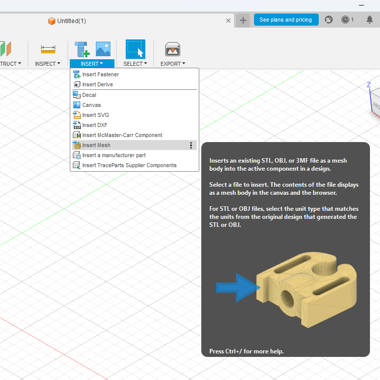
- Open Fusion 360.
- Go to Insert → Insert Mesh.
- Select your file (*.stl, *.obj, *.3mf).
- Position, scale, and rotate as needed.
- Click OK → The mesh will appear as a Mesh Body in the Browser.
👉 Fusion 360 categorizes meshes into Mesh Environment, separate from solids. You must convert if you want parametric editing.
3. Preparing Meshes for Conversion
Not all meshes can be converted directly. Common problems include:
- Too many facets (high-poly scans) → Heavy to compute.
- Non-manifold geometry → Holes, gaps, or intersecting surfaces.
- Noise from 3D scanning.
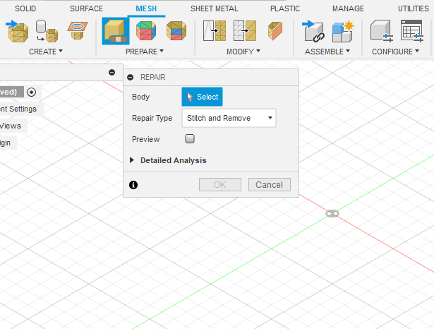
Tools for Preparation in Fusion 360:
- Repair: Mesh → Modify → Repair Body (fix holes, inverted normals).
- Reduce: Mesh → Modify → Reduce (lower facet count).
- Remesh: Create a more uniform distribution of triangles.
👉 Best practice: Aim for meshes under 10,000 faces for reliable conversion. Fusion 360 struggles with extremely detailed models.
4. Conversion Methods in Fusion 360
Fusion 360 provides multiple workflows depending on mesh quality and your design intent.
4.1 Direct Mesh to BRep Conversion
Best for low-poly meshes (e.g., simple STL models).
Steps:
- Right-click Mesh Body in Browser.
- Select Mesh to BRep.
- Choose target component.
- Click OK.
Fusion 360 converts the triangular mesh into a faceted solid body.
👉 Works well for mechanical parts with fewer faces. Doesn’t work well with large or scanned meshes.
4.2 Reduce + Convert Workflow
Best for medium complexity meshes.
Steps:
- Go to Mesh Workspace.
- Use Modify → Reduce.
- Reduce by percentage or target face count.
- Preserve shape while lowering polygon density.
- Right-click mesh → Convert Mesh.
- Choose Faceted (keeps triangles) or Prismatic (tries to rebuild CAD-like faces).
👉 Prismatic option attempts to identify flat and cylindrical faces—making it easier to edit.
4.3 Reverse Engineering Workflow
Best for 3D scans or organic models.
Instead of converting the mesh directly, you use it as a reference:
- Import mesh.
- Create sketches and features aligned to mesh geometry.
- Use Fit Face / Plane / Cylinder tools to approximate CAD features.
- Build a new parametric solid from scratch.
👉 Slower, but yields a cleaner, fully parametric model.
5. Handling High-Poly Meshes
3D scans often produce meshes with hundreds of thousands to millions of faces. Direct conversion will fail.
Strategies:
- Decimate in external software like Meshmixer, Blender, or MeshLab before importing.
- Use Region Grouping in Fusion 360 to identify flat/cylindrical faces.
- Convert only critical portions of the mesh.
- Consider Hybrid Modeling: Keep part as mesh, add features as solids.
6. Editing Converted Meshes
Once converted into a Solid Body (BRep), you can use standard Fusion 360 tools:
- Extrude, Cut, Fillet, Chamfer.
- Apply constraints and dimensions.
- Assemble with Joints.
- Run CAM toolpaths or Simulation.
👉 Keep in mind: Converted faceted solids may still look “blocky” unless you rebuild with parametric surfaces.
7. Best Practices
- Check mesh quality first – Repair before conversion.
- Reduce face count aggressively when possible.
- Choose Prismatic conversion for mechanical parts.
- Use reverse engineering for organic shapes.
- Hybrid workflow – Sometimes leave part of the model as mesh.
- Plan design intent – Are you just editing a 3D print, or fully engineering a part?
8. Real-World Applications
8.1 3D Scanning to CAD
- Example: Scan a broken mechanical part, convert to CAD, redesign, and manufacture replacement.
8.2 Editing Downloaded STL Models
- Example: Download a Thingiverse phone stand, convert to solid, add branding or mounting holes.
8.3 Manufacturing and CAM
- Example: Import an STL into Fusion 360, convert to solid, generate toolpaths for CNC machining.
8.4 Reverse Engineering Legacy Parts
- Example: A factory part has no drawings. Scan, convert, and rebuild as CAD for documentation.
9. Limitations of Mesh to Solid in Fusion 360
- Struggles with large high-poly meshes.
- Converted models may remain faceted, not smooth.
- Not suitable for organic surfaces (e.g., faces, statues).
- Requires cleanup for professional manufacturing.
10. Alternative Tools for Complex Mesh Workflows
Sometimes Fusion 360 isn’t enough. Other tools:
- Meshmixer – Free, great for mesh cleanup.
- Blender – Powerful for remeshing and sculpting.
- Geomagic Design X – Professional reverse engineering.
- SolidWorks ScanTo3D – Similar workflow.
👉 Fusion 360 is best for small-to-medium complexity parts.
11. Future of Mesh Workflows in Fusion 360
Autodesk is improving mesh handling:
- Better automatic face recognition.
- AI-powered mesh simplification.
- Improved hybrid modeling (mesh + solid together).
This trend makes Fusion 360 more powerful for reverse engineering and 3D scan workflows.
Conclusion
Converting meshes to solids in Fusion 360 bridges the gap between artistic/scanned geometry and engineering-ready CAD.
Key takeaways:
- Meshes (STL, OBJ) are great for visualization and printing but lack parametric control.
- Fusion 360 provides multiple conversion workflows:
- Direct Conversion – for simple meshes.
- Reduce + Convert – for medium complexity.
- Reverse Engineering – for high-poly or organic models.
- Always prepare and repair meshes before conversion.
- Be realistic about limitations—sometimes you must rebuild geometry from scratch.
By mastering Mesh to Solid conversion in Fusion 360, engineers and makers can unlock a world of possibilities: modifying 3D scans, editing STL models, preparing parts for CNC machining, and creating parametric designs from mesh data.