
In the world of 3D modeling, creating simple geometric shapes is straightforward. An extrude here, a revolve there, and you have a solid foundation. But what happens when you need to design something more complex, more organic? How do you create a smooth, elegant transition between a square base and a circular top, or model an ergonomic handle that flows perfectly into its housing? The answer lies in one of the most powerful and versatile tools in Autodesk Fusion 360: the Loft command.
The Fusion 360 loft feature is your key to unlocking a new level of design freedom, allowing you to build complex geometries that would be difficult or impossible to create with basic modeling operations. It’s the secret behind everything from sleek car bodies and aerodynamic aircraft wings to custom-fit ergonomic products.
This comprehensive guide is your ultimate fusion 360 loft tutorial. We will journey from the fundamental principles to advanced techniques, empowering you to confidently use this essential tool. We’ll cover creating your first simple loft, gaining precise control with guide rails and centerlines, troubleshooting common issues, and exploring real-world applications. By the end, you’ll be equipped to transform your creative visions into tangible, complex models.
Table of Contents
What is the Fusion 360 Loft Command? A Foundational Overview
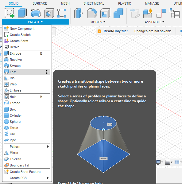
At its core, the loft command fusion 360 creates a transitional 3D shape between two or more 2D sketches, known as “profiles.” Imagine you have several cross-sectional slices of an object at different points. The Loft tool acts like a digital skin, stretching and wrapping a surface or solid body between these profiles to connect them seamlessly.
Think of it like building a ship’s hull. The shipwright first lays down a series of ribs (profiles), and then planks the hull over them, creating a smooth, continuous surface. The Loft feature works on a similar principle, but with the infinite precision of CAD software. This makes the loft feature explained a cornerstone of advanced 3D modeling loft techniques.
The key components you’ll work with are:
- Profiles: These are the closed or open 2D sketches that define the cross-sectional shape of your loft at different points. You need a minimum of two profiles to create a loft.
- Sketch Planes: Each profile must exist on its own sketch plane. These planes are often parallel but can also be angled to create more dynamic forms.
- Guide Rails/Centerline (Optional): These are additional sketches that guide the path and shape of the transition between profiles, offering a much higher degree of control over the final form.
Understanding these basic elements is the first step toward mastering the creation of sophisticated transition shapes.
Getting Started: Your First Loft in Fusion 360
Let’s dive in and create a simple loft. This hands-on exercise will demonstrate the fundamental workflow and help you understand how to use the loft tool in fusion 360. We’ll create a classic transition from a square to a circle.
Step 1: Creating Your Sketch Planes
Before you can draw your profiles, you need places to put them. The loft command requires profiles to be on separate planes.
- Start a New Design: Open Fusion 360 and start a new design.
- Create the First Sketch: Select one of the origin planes (e.g., the XY plane) and create a sketch. Draw a centered rectangle, say 50mm x 50mm. Click “Finish Sketch.”
- Construct an Offset Plane: To create a plane for our second profile, go to the
Constructmenu and selectOffset Plane. Select the same plane you just drew on (the XY plane). Drag the arrow or enter a distance, like 100mm, and click OK. You now have a new plane parallel to the first one.
Step 2: Drawing Your Profiles
Now that we have our sketch planes, it’s time to draw the cross-sectional shapes.
- Create the Second Sketch: Select the new offset plane you just created and click
Create Sketch. - Draw the Second Profile: Use the Circle tool to draw a centered circle with a diameter of 30mm. Ensure it’s roughly centered above the square from the first sketch.
- Finish Sketch: Click “Finish Sketch.” You should now see a square on the bottom plane and a circle on the top plane in your 3D view.
Step 3: Activating the Loft Command
With our profiles ready, it’s time for the magic to happen.
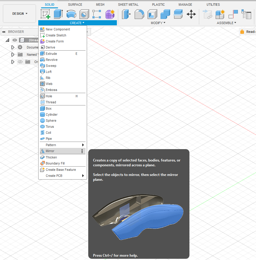
- Find the Loft Tool: Navigate to the
Createdropdown menu in theSolidorSurfacetab and selectLoft. - The Loft Dialog Box: A dialog box will appear. This is your control center for the entire operation. It will prompt you to select your profiles.
Step 4: Selecting Profiles and Finalizing the Loft
- Select Profiles: Click on the first profile (the square). It will highlight. Then, click on the second profile (the circle).
- Instant Preview: As soon as you select the second profile, Fusion 360 will generate a preview of the lofted shape. You’ll see a smooth transition from the square base to the circular top.
- Operation Type: Ensure the
Operationis set toNew Body. - Click OK: Click the OK button to finalize the command.
Congratulations! You have successfully created your first object using the Fusion 360 loft command. This simple exercise demonstrates the core power of the tool, but we’ve only scratched the surface.
Elevating Your Designs: Introducing Guide Rails
That first loft was great, but you probably noticed the transition was a straight, direct line between the two profiles. What if you want to control the curvature? What if you want the shape to bulge outwards or curve inwards? This is where guide rails come into play.
Guide rails are curves that connect the profiles and dictate the path the lofted surface must follow. They give you granular control over the shape’s contour, transforming a simple transition into a deliberately designed surface.
The Power of Control: Why Use Guide Rails?
Using guide rails is essential for:
- Defining Complex Curvature: Create non-linear, organic transitions.
- Preventing Twisting: Ensure the loft transitions smoothly without unexpected twists, especially between complex profiles.
- Matching Existing Geometry: Precisely match the lofted surface to adjacent features or bodies.
- Achieving Specific Aesthetics: Control highlights and reflections on the surface, which is critical in industrial design.
Practical Walkthrough: Creating a Loft with Guide Rails
Let’s modify our previous example to include guide rails for a more sculpted look. We’ll make our square-to-circle transition bow outwards.
- Set Up Profiles: Create the same 50mm square and 30mm circle on offset planes 100mm apart, just as before.
- Create a Perpendicular Sketch: Now, we need a new sketch plane that is perpendicular to our existing profile planes. The YZ or XZ origin plane should work perfectly. Select one and click
Create Sketch. - Draw the Guide Rails: Use the
Fit Point Splinetool for maximum control. Click on a point on the edge of the square, then click one or two points in the space between the profiles to define the outward curve, and finally click on the corresponding point on the circle to terminate the spline. It is crucial that the spline snaps to the geometry of both profiles. Repeat this process on the opposite side to create a symmetrical pair of guide rails. - Finish Sketch: Exit the sketch.
- Activate the Loft Command: Go to
Create > Loft. - Select Profiles First: Select the square and the circle for the
Profilesselection box. - Select Guide Rails: Click the
+button next toRailsin the dialog box. Now select the two splines you drew. You will immediately see the preview update, with the body bulging out to follow the path of your guide rails. - Finalize: Click OK.
You have now created a much more complex and controlled shape, demonstrating the true potential of the loft command fusion 360.
Advanced Lofting Techniques and Options
The Loft dialog box holds several other powerful options that allow for even more sophisticated parametric design.
The Centerline Option: A Different Kind of Guide
While guide rails control the outer surface, a centerline defines a path that the profiles follow. The profiles remain perpendicular to the centerline path. This is perfect for creating objects like custom pipework, bent handles, or ducting.
- How it works: You create your profiles on planes as usual, but then you also draw a single, open path (like a spline or arc) that represents the center flow of the object. In the Loft dialog, you select this path in the
Centerlinesection. The loft will then sweep the profiles along this path, transitioning between them as it goes.
Continuity and Tangency Control (G0, G1, G2)
In the Loft dialog, next to your selected profiles, you’ll see a Continuity dropdown. These settings control how the lofted surface connects to adjacent geometry. This is a key concept in professional surface modeling.
- Connected (G0): The default option. The lofted surface simply connects at the edge. There may be a sharp angle.
- Tangent (G1): The lofted surface will be tangent to the adjacent surface or sketch plane. This creates a smooth, seamless transition with no sharp edges. You can adjust a
Tangent Weightto control how much influence the tangency has. - Curvature (G2): This provides an even smoother transition by matching the curvature of the adjacent surface. It’s the highest quality connection, essential for creating Class-A surfaces in automotive and product design. For a deeper dive into surface continuity, the Autodesk Knowledge Network is an excellent resource.
Closed Lofts and Point Selections
The Loft tool isn’t limited to open-ended shapes. You can create closed loops or loft to a sharp point.
- Closed Loft: If you have three or more profiles arranged in a loop, you can select them in order and then check the
Closedoption in the dialog box to create a continuous, toroidal shape. - Loft to Point: You can select a sketch point as your final “profile.” This will cause the loft to converge to a sharp tip, perfect for creating things like cones, pyramids, or stylized spikes.
Common Problems and Troubleshooting: “Fusion 360 Loft Not Working”
Even experienced users run into issues. If you’re encountering errors, here are some common culprits and solutions for the dreaded “Fusion 360 loft not working troubleshooting” scenario.
Error: “The loft operation could not be completed”
This generic error can be frustrating, but it usually stems from one of a few issues:
- Self-Intersecting Geometry: Your guide rails might be too extreme, causing the resulting surface to fold back on itself. Try making your guide curves less dramatic.
- Guide Rails Not Touching Profiles: The endpoints of your guide rails must be coincident with the profiles they are meant to guide. Zoom in and ensure they are properly snapped.
- Incorrect Profile Selection Order: For lofts with more than two profiles, the order in which you select them matters. Select them sequentially from one end to the other.
Unwanted Twisting in Your Loft
Sometimes a loft between two complex profiles will result in an ugly, twisted shape. This is because Fusion 360 is making its best guess about how to connect the vertices between profiles.
- Solution: You can manually control the connection points. After selecting your profiles, you’ll see connector points on them. You can drag these points around the profile to different vertices to untwist the loft and achieve the desired flow. For ultimate control, use at least one guide rail.
Profiles Not Showing Up for Selection
If you can’t select a sketch as a profile, check the following:
- Sketch Visibility: Ensure the sketch containing the profile is visible in the browser tree (the eye icon is on).
- Closed Profiles for Solids: If you are in the
Solidtab, your profiles must be closed loops. If there’s a tiny gap in your sketch, it won’t be selectable for a solid loft. Use theSurfacetab if you intend to work with open profiles.
Real-World Applications of the Fusion 360 Loft
The theory is great, but where does the Fusion 360 loft command shine in practice? It’s used everywhere when creating complex shapes with fusion 360 loft is a requirement.
Product Design: Ergonomic Handles and Housings
Think of a power drill, a comfortable mouse, or a kitchen utensil handle. These objects often feature complex, flowing shapes that transition to fit the human hand. Lofts are the perfect tool for creating these ergonomic surfaces, often using multiple profiles and intricate guide rails.
Aerospace and Automotive: Aerodynamic Surfaces
The sleek, efficient shapes of aircraft fuselages, wings, and modern car bodies are prime examples of lofting. Engineers use precisely defined cross-sections (profiles) and guide curves to create surfaces that minimize drag and maximize performance. The principles of aerodynamics, as detailed by sources like NASA’s Glenn Research Center, are physically modeled using tools like Loft.
Art and Sculpture: Organic Forms
For digital artists and sculptors, the loft command is a gateway to creating fluid, organic forms that would be nearly impossible to model otherwise. It allows for an intuitive way to build up complex shapes that mimic forms found in nature.
Fusion 360 Loft vs. Other Commands: When to Choose Loft
Understanding when to use Loft versus other modeling tools is key to an efficient workflow. It’s a fundamental aspect of understanding parametric modeling principles.
Loft vs. Sweep
- Sweep: A sweep takes a single profile and moves it along a path. The profile’s shape does not change. Use this for creating pipes, wires, or moldings where the cross-section is constant.
- Loft: A loft transitions between multiple, different profiles. Use this when the object’s cross-sectional shape changes along its length.
Loft vs. Extrude
- Extrude: An extrude takes a single profile and projects it linearly in a single direction. It’s the most basic 3D operation.
- Loft: A loft can follow a non-linear path (with a centerline) and change its shape dramatically from start to finish.
Conclusion: Go Forth and Create
The Fusion 360 loft command is far more than a simple feature; it’s a gateway to advanced modeling and a fundamental tool for creating sophisticated, real-world designs. We’ve journeyed from the basics of selecting profiles on different sketch planes to the nuanced control offered by guide rails and the centerline method.
By understanding how to build a basic loft, control its form, troubleshoot common problems, and know when to use it over other commands, you have added a powerful skill to your design arsenal. The key to mastery is practice. Experiment with different shapes, push the limits of guide rail curvature, and explore the various continuity options. Start by modeling objects around you—a bottle, a tool handle, a speaker casing—and you’ll soon find the loft command becoming an intuitive and indispensable part of your creative process.