
From the intricate clockwork of a Swiss watch to the powerful transmission of a race car, gears are the unsung heroes of mechanical engineering. They transmit power, change speed, and alter direction with remarkable precision. For designers, engineers, and hobbyists, creating accurate and functional gears can be a daunting task. The complex geometry, critical tolerances, and precise calculations have historically been a significant barrier. But what if you could harness the power of advanced CAD software to make the process intuitive, fast, and incredibly accurate? Welcome to the world of designing Fusion 360 gears.
Autodesk Fusion 360 has revolutionized how we approach mechanical design, and its capabilities for gear creation are second to none. Whether you’re a seasoned professional designing a complex planetary gearbox or a hobbyist 3D printing parts for a personal project, Fusion 360 provides the tools you need to succeed. This comprehensive guide will walk you through everything you need to know. We’ll start with the fundamentals, explore the powerful built-in gear generators, dive into advanced techniques for creating custom gear trains, and finally, bridge the gap from digital design to physical manufacturing. Get ready to master the art and science of gear design in the most powerful cloud-based CAD platform available.
Table of Contents
Why Fusion 360 is a Game-Changer for Gear Design
Before we dive into the nuts and bolts (or rather, teeth and cogs), it’s essential to understand why Fusion 360 stands out as the premier choice for this task. It’s not just another piece of CAD software; its entire ecosystem is built for modern engineering workflows.

An Integrated CAD/CAM/CAE Environment
Fusion 360 isn’t just for modeling. It’s a unified platform that combines Computer-Aided Design (CAD), Computer-Aided Manufacturing (CAM), and Computer-Aided Engineering (CAE). This means you can:
- Design: Model your gears and assemblies with precision.
- Simulate: Use motion studies to see how your gears will interact and perform under load, identifying potential issues before you ever create a physical part.
- Manufacture: Generate toolpaths for CNC machining or prepare your models for 3D printing directly within the same software, ensuring a seamless transition from screen to reality.
This integrated approach saves immense time and reduces the risk of errors that can occur when transferring files between different software packages.
The Power of Parametric Modeling
At its core, Fusion 360 is a powerful parametric modeling tool. Every feature you create is based on parameters—dimensions, constraints, and relationships. When you design a gear, this means you can easily change a single parameter, like the number of teeth or the module, and the entire model will automatically update to reflect that change. This is incredibly powerful for iterating on designs, testing different gear ratios, and optimizing your mechanical systems without having to start from scratch.
A Thriving Ecosystem of Add-ins and Scripts
One of Fusion 360’s greatest strengths is its extensibility. The Autodesk App Store is filled with powerful add-ins and scripts created by both Autodesk and the community. For gear design, this is a massive advantage. Instead of manually sketching complex involute curves for each tooth, you can use a dedicated Fusion 360 add-in for gears to generate perfect geometry in seconds, based on standard engineering parameters. We’ll explore this in detail shortly.
Understanding the Anatomy of a Gear: Key Terminology
To effectively design gears, you must speak the language. Understanding the core terminology is crucial for using gear generators correctly and for troubleshooting any issues with meshing. Here are the essential terms you’ll encounter when designing gears in Fusion 360.
- Module (m): This is arguably the most important gear parameter. It’s a unit of size that defines the gear’s tooth proportions. For two gears to mesh correctly, they must have the same module. It’s calculated as the pitch diameter divided by the number of teeth.
- Pitch Diameter (d): The diameter of the imaginary circle where two gears effectively make contact. It’s the fundamental circle used for all gear calculations.
Pitch Diameter = Module × Number of Teeth. - Pressure Angle: The angle between the line of force acting between meshing teeth and the line tangent to the pitch circles. Common pressure angles are 14.5°, 20° (most common), and 25°. For gears to mesh, they must also share the same pressure angle.
- Number of Teeth (z or N): Simply the total count of teeth on the gear. This directly influences the gear’s diameter and the final gear ratio.
- Addendum: The radial distance from the pitch circle to the top of a tooth.
- Dedendum: The radial distance from the pitch circle to the bottom of a tooth space.
- Backlash: The small amount of clearance or “play” between the teeth of meshing gears. Some backlash is necessary to prevent binding, especially in applications like 3D printing gears, where manufacturing tolerances aren’t perfect. A value of zero means no clearance.
- Center Distance (a): The distance between the centers of two meshing gears. For standard spur gears, it’s calculated as:
Center Distance = (Pitch Diameter of Gear 1 + Pitch Diameter of Gear 2) / 2.
Familiarizing yourself with these terms will make the next step—actually creating the gears—a much smoother process.
The Easy Way: Using the Fusion 360 Gear Generator Add-in
Now for the magic. The most efficient way to create a standard spur gear in Fusion 360 is by using a script or an add-in. The most popular and reliable one is the “Spur Gear” add-in, readily available to all users.
Step 1: Finding and Installing the Spur Gear Add-in
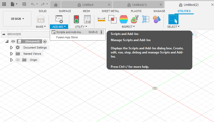
In modern versions of Fusion 360, this script is often included by default. Here’s how you access it:
- Navigate to the UTILITIES tab in the main toolbar.
- Click on the ADD-INS panel and select Scripts and Add-Ins.
- In the dialog box, you’ll see two tabs: “My Scripts” and “Sample Scripts”.
- The Spur Gear generator is typically located under the “Sample Scripts” tab in a Python folder. Select “SpurGear” and click Run.
If for some reason you cannot find it, you can download it and other gear generators from the Autodesk App Store. Once you run the script, a dialog box will appear, which is your control panel for creating the gear.
Step 2: A Walkthrough of the Spur Gear Generator Dialog Box
This dialog box is where you’ll input the parameters we just discussed. Let’s break down each option in the Fusion 360 gear generator:
- Pressure Angle: Choose from standard options like 20 or 14.5 degrees. 20 degrees is the modern standard, offering stronger teeth.
- Module: Enter the module for your gear. Remember, this must be consistent across all meshing gears.
- Number of Teeth: Input the desired number of teeth for this specific gear.
- Backlash: Input the clearance you want between teeth. For CNC machined parts, this can be very small. For 3D printing, a value like 0.1mm or 0.2mm is a good starting point to compensate for filament extrusion variations.
- Root Fillet Radius: This adds a small, rounded corner at the base of the tooth, which significantly increases its strength by reducing stress concentration. It’s highly recommended to use this.
- Gear Thickness: This defines the face width, or the Z-axis height, of the gear.
- Hole Diameter: The diameter of the central bore for mounting the gear on a shaft.
As you adjust these values, Fusion 360 provides a real-time preview of the pitch diameter. This is a fantastic feature for quickly verifying your design before committing.
Step 3: Generating and Refining Your First Gear
Once you’re satisfied with the parameters, click “OK”. Fusion 360 will automatically generate a new component in your browser tree containing a perfectly formed gear body. This component is a standard solid body, meaning you can now perform any additional operations on it. You can:
- Add a keyway or a set screw hole to the central bore.
- Use the Shell command to hollow it out and save material.
- Add chamfers or fillets to the edges for a more finished look.
This process answers the common question of “how to make a gear in Fusion 360” in the most efficient way possible, giving you a perfect foundation for more complex assemblies.
Beyond the Basics: Advanced Gear Design Techniques
While the generator is perfect for individual spur gears, real-world designs often involve more complexity. Here’s how to take your Fusion 360 gears to the next level.
Designing a Complete Gear Train
A gear train is simply two or more gears working together. To create one in Fusion 360, you’ll generate each gear as a separate component using the add-in. The key is ensuring they mesh correctly.
- Calculate the Center Distance: Use the formula mentioned earlier to find the exact distance required between the gear centers.
a = m * (z1 + z2) / 2. - Position the Gears: Create a base sketch and draw two circles representing the shaft holes, separated by the calculated center distance. Extrude this base plate.
- Assemble with Joints: Use Fusion 360’s “As-built Joint” or “Joint” feature to place your gear components. Use a “Revolute” joint to fix each gear to its respective axle location on the base plate. This allows them to rotate but not move linearly.
- Simulate with Motion Links: To make the gears turn together realistically, go to ASSEMBLE > Motion Link. Select the two revolute joints you just created. Fusion 360 will automatically calculate the correct gear ratio in the dialog box based on the pitch diameters. Now, when you click and drag one gear, the other will rotate in perfect sync!
This process is invaluable for visualizing your mechanism and calculating gear ratios in Fusion 360‘s simulation environment.
Customizing Gear Profiles
The Spur Gear add-in creates gears with a standard involute tooth profile, which is ideal for most applications. However, for specialized designs like clock escapements or non-standard profiles, you may need to model teeth manually. This is an advanced technique that involves:
- Sketching the precise involute curve using equations or a three-point arc approximation.
- Creating a single tooth profile.
- Extruding the single tooth.
- Using the “Circular Pattern” feature to create the remaining teeth around the gear blank.
While more complex, this demonstrates the true flexibility of Fusion 360’s core modeling tools.
Creating Other Gear Types (Bevel, Worm, Helical)
The default add-in is limited to spur gears. Creating other types requires more direct modeling techniques:
- Helical Gears: Can be created by modeling a spur gear and then using the “Twist” feature (found within the Move/Copy tool) or by sweeping a tooth profile along a helical path.
- Bevel Gears: These require using the “Loft” command to create a tooth profile that tapers from a large end to a small end.
- Worm Gears: These are the most complex and typically involve using the “Coil” command to create the worm and complex surfacing techniques for the worm wheel.
Several more advanced add-ins are available on the App Store to assist with these gear types.
From Digital to Physical: Manufacturing Your Fusion 360 Gears
A design is only as good as its physical counterpart. Fusion 360’s integrated CAM makes manufacturing your gears incredibly straightforward.
Preparing Gears for 3D Printing
For prototyping and many low-load applications, 3D printing is the ideal manufacturing method.
- Material Choice: PLA is fine for light-duty models, but for functional parts, consider PETG for its durability or Nylon for its excellent wear resistance and low coefficient of friction. For a deep dive into functional materials, resources like All3DP offer excellent guides.
- Print Orientation: Always print gears flat on the build plate (laying on their face). This ensures the layer lines are aligned for maximum tooth strength.
- Settings: Use a smaller layer height (e.g., 0.12mm) for a more accurate tooth profile. A higher infill percentage (50% or more) is recommended for strength.
- Tolerances: This is where the backlash parameter becomes critical. 3D printers have inherent inaccuracies. Adding 0.1mm-0.2mm of backlash in the design phase provides the necessary clearance to prevent the printed gears from binding.
Once designed, you can simply right-click the component and select “Save as Mesh” to export an STL file ready for your slicer software.
CNC Machining Gears
For high-strength, high-precision applications, you’ll want to machine your gears from metal (like aluminum or steel) or a robust plastic (like Delrin or PEEK). The process in Fusion 360 is:
- Switch to the MANUFACTURE workspace.
- Create a new Setup, defining your stock material and work coordinate system.
- Use CAM strategies like 2D Adaptive Clearing to rough out the material and 2D Contour or Trace to precisely finish the tooth profiles.
- Simulate the toolpath within Fusion 360 to verify the operation and check for collisions.
- Post-process the code for your specific CNC machine.
This all-in-one workflow is a key reason why professionals rely on Fusion 360 for creating robust mechanical components like those outlined in engineering resources like the Machinery’s Handbook.
Common Pitfalls and Troubleshooting Tips
Even with powerful tools, you might run into issues. Here are some common problems and their solutions:
- Problem: My gears are binding or not meshing smoothly.
- Solution: Check three things: 1) The Module must be identical. 2) The Pressure Angle must be identical. 3) The Center Distance must be exact. If it’s a 3D print, you likely need to increase the Backlash value in the generator and try again.
- Problem: The Spur Gear Add-in won’t run or gives an error.
- Solution: Ensure your Fusion 360 is up to date. Sometimes, updates can temporarily break scripts. You can also try re-downloading the script from the App Store.
- Problem: My gear train simulation is slow or lagging.
- Solution: Complex assemblies with many moving parts can be computationally intensive. Try simplifying your model by suppressing non-essential components or using the “Simplify” tool to reduce mesh complexity before running a motion study.
- Problem: My 3D printed gear teeth are weak and break off.
- Solution: This is almost always due to print orientation. Ensure you are printing the gear flat on its face. Also, consider using a stronger material like PETG or Nylon and increasing your print temperature slightly for better layer adhesion.
Conclusion: Your Journey into Gear Design Starts Now
Designing Fusion 360 gears transforms a once-complex engineering challenge into an accessible and even enjoyable process. By leveraging the parametric power of the software and the efficiency of the Spur Gear add-in, you can quickly move from concept to functional prototype. We’ve covered the essential terminology, provided a step-by-step guide to generating gears, explored how to assemble and simulate a complete gear train, and outlined the path to manufacturing your designs through 3D printing or CNC machining.
The true power of Fusion 360 lies in its ability to integrate all these steps into a single, seamless workflow. The next time your project requires the precise transfer of motion, you’ll be fully equipped to design the perfect gears for the job. Open up Fusion 360, run the gear generator, and start experimenting. The possibilities are limitless.