
Welcome to the world of parametric 3D modeling, where precision, control, and efficiency reign supreme. If you’ve ever found yourself wrestling with a complex sketch in Autodesk Fusion 360, battling confusing profiles, or watching your model break after a simple dimension change, you’ve likely overlooked one of the most powerful tools in your arsenal: the Fusion 360 construction line.
Think of construction lines as the invisible scaffolding of your design. They are the secret framework that holds everything together, providing structure, defining relationships, and guiding your geometry without becoming part of the final, solid model. They are the difference between a fragile, chaotic sketch and a robust, intelligent, and easily editable design.
This comprehensive guide is designed to take you from a novice to an expert in using construction geometry. We’ll dive deep into not just how to create them, but why they are a non-negotiable element of professional CAD work. You will learn:
- What a Fusion 360 construction line is and its fundamental purpose.
- Why they are critical for creating stable, parametric modeling in Fusion 360.
- Step-by-step methods for creating and converting construction lines.
- Advanced techniques, including using them for complex constraints and projecting geometry.
- Common mistakes to avoid that will save you hours of frustration.
By the end of this article, you’ll view construction lines not as an optional feature, but as the foundational pillar for all your future designs.
Table of Contents
What is a Fusion 360 Construction Line, Really?
At its core, a Fusion 360 construction line is a type of line or curve within a sketch that serves purely as a reference. Unlike standard (or ‘model’) geometry, which is represented by solid blue or black lines, construction geometry is visually distinct, appearing as a dashed line.
This visual difference is crucial because it signals to both you and the software that this line is not meant to create a closed profile for extrusion, revolution, or other solid-forming features. Its sole job is to help you build your actual model geometry with precision.
Think about it this way: when an architect designs a building, they first draw grid lines, centerlines, and reference points. These lines aren’t part of the final building’s walls or floors, but they are essential for ensuring everything is placed correctly. That is precisely what is the purpose of a construction line in Fusion 360—it’s your digital gridline, your centerline, your geometric guide.
Why Construction Lines are Non-Negotiable for Professional CAD Work
Moving beyond the basic definition, understanding why construction lines are so vital is key to unlocking their potential. Their use is a hallmark of an experienced CAD user because they directly contribute to creating more intelligent and manageable designs.
The Foundation of Parametric Modeling
Fusion 360 is a parametric modeling tool, meaning your design is driven by parameters and relationships. Construction lines are the backbone of this system. They allow you to establish relationships—like symmetry, tangency, or specific distances—that drive the model’s behavior. When you change a dimension, the parametric modeling in Fusion 360 engine recalculates the design, and it’s the underlying construction geometry that ensures everything updates predictably.
Achieving Fully Constrained Sketches
A ‘fully constrained’ sketch (indicated by all black lines) is the gold standard in CAD. It means every piece of geometry is locked in place and cannot move unexpectedly. Achieving this without a cluttered mess of dimensions is often impossible without construction lines. You can use them to:
- Lock a point to the origin.
- Define the angle of a feature relative to an axis.
- Create a centerline to constrain two elements symmetrically.
- Establish a midpoint relationship without having to draw a physical line.
Mastering Fusion 360 sketch constraints is fundamentally tied to mastering the use of construction lines. They provide the anchors for your constraints to attach to.
Reducing Sketch Complexity
Imagine trying to create a gear without construction lines. You’d have solid circles defining the pitch diameter, root diameter, and outside diameter, all creating a confusing web of overlapping profiles. It becomes a nightmare to select the correct profile for extrusion.
By making the reference circles for pitch and root diameters construction geometry, you are left with only one clean, selectable profile for the gear tooth. This practice keeps your primary profile clean and unambiguous, which is essential for complex Fusion 360 sketch geometry.
Creating Symmetrical and Patterned Designs
Construction lines excel as axes of symmetry. By drawing a construction line and using the Mirror constraint, you can draw one half of a complex part and have the other half created automatically and perfectly mirrored. This not only saves immense time but also guarantees perfect symmetry. Similarly, they are used as paths for circular and rectangular patterns, ensuring precise and controlled repetition of features.
How to Use Construction Lines in Fusion 360: A Step-by-Step Guide
Now that you understand the ‘why’, let’s get into the practical ‘how’. There are two primary ways to create construction geometry in Fusion 360, and knowing both will make your workflow incredibly efficient.
Method 1: Toggling Construction Mode Before Drawing
This is the most straightforward method when you know in advance that you need to draw reference geometry.
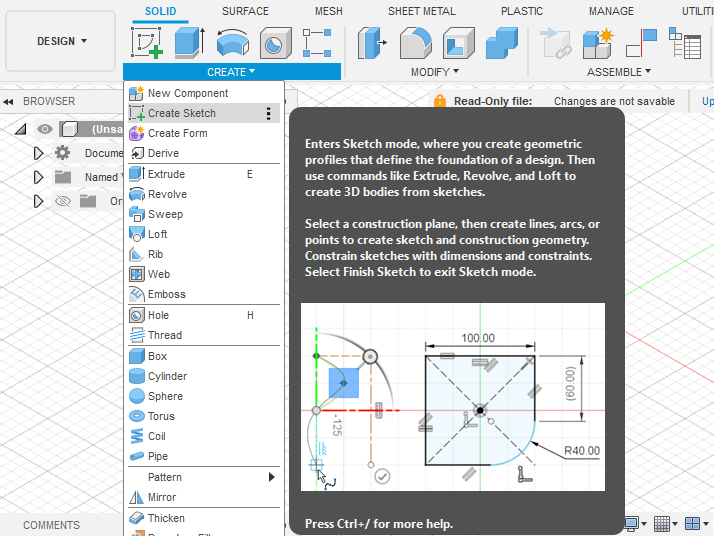
- Enter a Sketch: Create a new sketch on a plane or face.
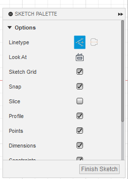
- Open the Sketch Palette: Look for the dialog box that appears, usually on the right side of your screen. If it’s not visible, go to
View > Show Sketch Palette. - Activate Construction Mode: In the Sketch Palette, under ‘Options’, you’ll see an icon that looks like a line with two perpendicular lines on either side. This is the ‘Construction’ button. Click it. The icon will be highlighted in blue.
- Use the Keyboard Shortcut (Recommended): The fastest way to toggle construction mode on and off is by pressing the ‘X’ key on your keyboard. This is a workflow game-changer.
- Draw Your Geometry: With construction mode active, any line, circle, arc, or rectangle you draw will automatically be created as a dashed construction line.
- Deactivate Construction Mode: Simply press the ‘X’ key again or click the icon in the Sketch Palette to return to drawing standard model geometry.
Method 2: Converting Existing Lines to Construction Geometry
Often, you’ll draw a line and later realize it should have been a reference line. Fusion 360 makes this incredibly easy to fix.
This section directly answers the common question: how to change a line to a construction line in Fusion 360?
- Select the Geometry: In your sketch, click on the existing solid line (or lines) you want to convert. You can hold
ShiftorCtrl(Cmdon Mac) to select multiple entities. - Press the ‘X’ Key: With the geometry selected, simply press the ‘X’ key. The solid line(s) will instantly transform into dashed construction lines.
- Use the Sketch Palette: Alternatively, with the geometry selected, you can click the ‘Construction’ icon in the Sketch Palette. The result is the same.
This ability to toggle back and forth is incredibly flexible, allowing you to change your design intent on the fly without deleting and redrawing.
Practical Example: Creating a Centered Flange
Let’s apply this to a real-world scenario. Imagine you need to model a simple flange with four bolt holes, perfectly centered on the origin.
- Create Centerlines: Start a new sketch. Press ‘X’ to enter construction mode. Draw one vertical and one horizontal Fusion 360 construction line that pass directly through the sketch origin. These now act as your permanent X and Y axes.
- Define Hole Placement: Still in construction mode, draw a circle centered at the origin. This circle’s diameter will define the placement of your bolt holes. This is often called a ‘Pitch Circle Diameter’ (PCD).
- Exit Construction Mode: Press ‘X’ again to switch back to drawing solid lines.
- Draw the Flange Body: Draw two concentric circles centered at the origin for the inner and outer diameters of the flange.
- Place the First Hole: Draw a small, solid circle for the first bolt hole. Use a ‘Coincident’ constraint to lock its center to the construction circle you drew in Step 2. Use a ‘Vertical’ constraint to lock its center to the vertical construction line. It’s now fully defined.
- Pattern the Holes: Use the ‘Circular Pattern’ tool. Select the solid hole circle as the ‘Object’ and the origin point as the ‘Center Point’. Set the quantity to 4.
Now, you can extrude the flange profile. Notice how clean the sketch is. The centerlines and PCD circle provided all the necessary references without cluttering the final profile. If you need to change the bolt hole spacing, you just change the dimension of the one construction circle, and all four holes update parametrically. This is the power of a fully constrained sketch built on construction geometry.
Advanced Techniques and Best Practices for Construction Geometry
Once you’re comfortable with the basics, you can start leveraging construction lines for more advanced tasks. These techniques separate proficient users from true experts.
Using Construction Lines for Complex Constraints
Construction lines are invaluable for setting up geometric relationships that aren’t immediately obvious. For example:
- Tangency: To make a line tangent to two circles without touching them, you can draw a construction line between the circle centers and use it to build the tangent relationship.
- Angles: Need to define a feature at a 30-degree angle from a non-orthogonal edge? Draw a construction line from the edge and another for your feature, then dimension the angle between them.
- Offset: The offset tool can create a construction line as an offset from a solid profile, perfect for defining a clearance or a boundary path for a tool to follow.
The Power of Projecting Geometry as Construction
When working with multi-part designs or complex bodies, you often need to reference geometry from another body or sketch. The ‘Project’ tool (keyboard shortcut ‘P’) is essential for this.
When you project an edge from another body into your active sketch, you have the option to bring it in as construction geometry. This is incredibly powerful. It allows you to, for instance, project the outline of a mounting plate into a new sketch to perfectly position the holes on a new part that will attach to it. Since the projected lines are construction lines, they act as perfect guides without interfering with your new sketch’s profiles. This is a cornerstone of robust assembly modeling and a key use of project geometry.
Best Practices for Construction Geometry Checklist
To solidify your understanding, here are some best practices for construction geometry that you should always follow:
- Centerlines First: When starting a symmetrical sketch, always begin by drawing a construction line for your axis of symmetry.
- Lock to the Origin: Use construction lines to connect your sketch to the origin. This is the first and most important step in constraining your sketch.
- Keep Profiles Simple: Your final, extrudable profiles (solid lines) should be as clean and simple as possible. Offload all supporting geometry to construction lines.
- Embrace the ‘X’ Key: Get comfortable using the ‘X’ key. Toggling between construction and solid geometry should become second nature.
- Don’t Fear Complexity: It’s better to have a dozen clear construction lines defining your intent than one messy solid profile that’s hard to control.
Common Mistakes to Avoid
Understanding common pitfalls can save you significant time and frustration. Here are the top mistakes users make with construction lines.
Mistake 1: Forgetting to Toggle Construction Mode Off
This is the most frequent error. You finish drawing your reference geometry and forget to press ‘X’. You then draw a critical part of your main profile as a construction line. When you go to extrude, you find you have an open loop that can’t be turned into a solid. The fix is simple: select the dashed line that should be solid and press ‘X’ to convert it back.
Mistake 2: Using Solid Lines for Reference Geometry
The opposite of mistake #1. Users draw centerlines or reference circles as solid lines. This creates multiple, nested closed profiles. When they try to extrude, Fusion 360 doesn’t know which area to select, or the user has to painstakingly click multiple tiny profile segments. This leads to messy, unpredictable models.
Mistake 3: Underutilizing Them for Constraints
Many users fail to use construction lines to their full potential for creating a fully constrained sketch. They might use them for a centerline but then rely on dozens of numerical dimensions for everything else. This creates a brittle sketch. A better approach is to use construction lines to define geometric relationships (e.g., this point is vertically aligned with that point) first, which often reduces the number of dimensions needed and makes the sketch more robust.
The Broader Context: Construction Geometry in CAD
It’s important to note that this concept is not unique to Fusion 360. The principle of separating model geometry from reference/construction geometry is a fundamental concept in nearly all professional CAD software, including SolidWorks, Inventor, and CATIA. Understanding this principle in Fusion 360 provides you with a transferable skill that is applicable across the entire engineering and design industry. The underlying standards for clear design intent are universal, often guided by principles laid out in standards like ASME’s Geometric Dimensioning and Tolerancing (GD&T).
For more direct information, the Autodesk Fusion 360 official documentation is always a valuable resource. Furthermore, the principles of clear geometric definition are taught in foundational engineering courses worldwide.
Conclusion: Build Smarter, Not Harder
The Fusion 360 construction line is far more than a simple drawing aid; it is the language of design intent. It’s how you communicate relationships, symmetry, and structure to the software, enabling the true power of parametric 3D modeling.
By embracing construction geometry, you are fundamentally shifting from merely ‘drawing’ shapes to ‘engineering’ intelligent systems. Your sketches will become cleaner, your models more robust and easier to edit, and your overall workflow will become dramatically more efficient.
So, the next time you begin a new sketch in Fusion 360, make your first action a deliberate one: press the ‘X’ key. Start with your framework, your scaffolding, your construction lines, and build your design on a foundation of precision and control. Your future self will thank you.