
Introduction
When working in Autodesk Fusion 360, your ability to view and navigate your 3D model efficiently is as important as modeling itself. A well-controlled camera lets you inspect designs from every angle, identify design issues, and prepare professional visuals for clients or teammates.
Fusion 360 camera system is built around an intuitive yet powerful set of viewing and navigation tools that mimic real-world camera behavior—orbit, pan, zoom, and perspective. Whether you’re modeling a complex mechanical assembly, a sculpted product form, or a PCB enclosure, mastering these camera controls ensures speed, precision, and clarity in your workflow.
In this article, we’ll explore:
- The fundamentals of Fusion 360’s camera system
- Different view types (orthographic, perspective, and custom)
- How to use orbit, pan, and zoom effectively
- The ViewCube and Named Views
- Section and visual styles for inspecting geometry
- Setting up camera positions for rendering and presentations
- Keyboard shortcuts and productivity hacks
By the end, you’ll be able to handle Fusion 360’s camera like a professional cinematographer—keeping your design always in focus.
Table of Contents
1. Understanding the Fusion 360 Camera
Fusion 360 uses a virtual camera to define how you see your model in the workspace. The camera has:
- Position: Where it is in 3D space.
- Target: The point it looks at (often the model’s center).
- Lens type: Perspective or orthographic projection.
When you orbit, pan, or zoom, you’re actually moving or rotating this camera relative to the model.
Two Camera Projection Modes
- Perspective
- Simulates a real camera lens.
- Objects farther away appear smaller.
- Great for realistic visualization and rendering.
- Orthographic
- Parallel projection with no depth distortion.
- All lines stay true to scale.
- Ideal for technical drawings and precise alignment.
You can toggle between them using:
Display Settings → Camera Type → Perspective/Orthographic.
2. Basic Camera Navigation Controls
Mastering navigation is the first step toward smooth modeling.
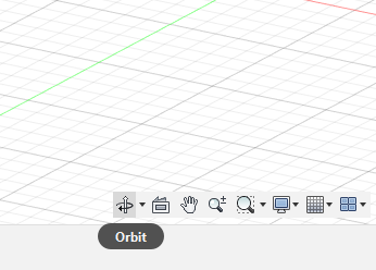
2.1 Orbit
Rotates the camera around the target point.
- Shortcut: Hold Shift + Middle Mouse Button (MMB).
- Alternative: Click and hold the Orbit icon in the Navigation Bar (bottom center).
- Tips:
- Use Constrained Orbit to limit rotation around vertical/horizontal axes.
- Use Free Orbit for unrestricted movement.
2.2 Pan
Moves the camera parallel to the viewing plane.
- Shortcut: Hold Middle Mouse Button and drag.
- Useful for shifting your focus without rotating.
2.3 Zoom
Moves the camera closer or farther from the target.
- Mouse Scroll Wheel – scroll up/down.
- Double-click middle mouse button to zoom and center on a selected face or body.
- Zoom Window: Drag a box around an area to zoom into it precisely.
2.4 Look At Command
Centers the camera on a selected face or plane.
- Right-click a face → Look At.
- Automatically aligns the camera normal to that surface—perfect for sketching.
3. The ViewCube – Your Navigation Companion
The ViewCube (top-right corner) provides quick access to standard orthographic views: Front, Top, Right, Left, etc.
Key Actions:
- Click faces, edges, or corners → instantly snap to that view.
- Click the Home icon to return to the default isometric orientation.
- Right-click the cube →
- Set Current View as Home
- Orthographic/Perspective Toggle
- Fit to View
Custom Home View
- Position the model as desired.
- Right-click the ViewCube → Set Current View as Home.
Now pressing Home or clicking the house icon always returns you here.
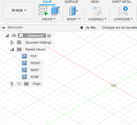
4. Using Named Views
Fusion 360 lets you save custom camera angles as Named Views—ideal for presentations and documentation.
Creating a Named View
- Adjust your camera angle.
- Open Browser → Named Views.
- Click + (New View).
- Give it a descriptive name, e.g., Front Detail, Exploded View.
Benefits
- Switch instantly between critical design angles.
- Maintain consistent visuals for renders or animations.
- Export screenshots or renderings with identical framing.
5. Camera Settings and Display Options
Under the Display Settings (monitor icon) at the bottom-center toolbar, you’ll find controls that affect visual clarity.
Key Camera-Related Settings
- Camera Type: Perspective or Orthographic.
- Visual Style: Shaded, Shaded with Hidden Edges, Wireframe, etc.
- Environment & Background: White, Gradient, or Photo-based HDRI.
- Ground Plane & Shadows: Helps give spatial context.
- Object Visibility: Toggle origins, sketches, joints, or bodies for a clean view.
These settings help tailor your viewing experience for design, review, or presentation.
6. Section Views – Seeing Inside Your Model
Sometimes you need to inspect internal components. Fusion 360’s Section Analysis tool lets you slice through solids dynamically.
Creating a Section View
- Go to Inspect → Section Analysis.
- Select a plane, face, or construction plane.
- Adjust the direction and offset.
- Click OK.
The camera now displays a live cut through your model.
You can hide/show the analysis anytime via Browser → Analysis Folder.
Pro Tip: Use orthographic projection for section views—ensures undistorted measurements.
7. Camera Control Shortcuts
Efficient modeling means keeping one hand on the mouse and one on the keyboard. Here are essential navigation shortcuts:
| Function | Shortcut |
|---|---|
| Orbit | Shift + Middle Mouse Button |
| Pan | Middle Mouse Button |
| Zoom | Scroll Wheel |
| Fit to View | F |
| Look At | Right-click → Look At |
| Home View | Shift + N |
| Toggle Orthographic/Perspective | ViewCube Right-click |
| Zoom Window | Z + Drag Box |
Pro Tip: Practice continuous navigation—Orbit → Zoom → Pan → Sketch. This fluid motion dramatically speeds up modeling.
8. Camera in Rendering & Animation Workspaces
The same camera tools extend to Fusion 360’s Render and Animation environments.
8.1 Render Camera Setup
- Switch to the Render Workspace.
- Use Named Views or manually set your camera angle.
- In Render Settings, you can:
- Lock the camera to prevent accidental movement.
- Choose Perspective or Orthographic projection.
- Adjust Field of View (FOV) for cinematic depth.
- Define Focal Length (shorter for wide angle, longer for zoom).
Tip: A 35 mm focal length gives a natural look, while 70–90 mm provides dramatic close-ups.
8.2 Depth of Field
Simulates focus blur. Activate under Render → Scene Settings → Depth of Field and set a focal point on your model. It adds realism for product visualizations.
8.3 Animation Camera
The Animation Workspace lets you create motion sequences.
Here, camera control defines the storytelling:
- Animate Camera Path: Move camera between Named Views.
- Keyframes: Set starting and ending camera positions.
- Playback Controls: Preview camera transitions smoothly.
You can create fly-throughs, exploded views, or assembly sequences for presentations.
9. Advanced Camera Features
9.1 Locking the Camera
Avoid accidental movement during rendering:
- Right-click Named View → Lock Camera.
- Prevents navigation changes until unlocked.
9.2 Camera Roll
Rotates the camera about its viewing axis (like tilting your head).
- Hold Shift + Alt + Middle Mouse and move left/right.
9.3 Setting Up Orthographic Drawings
For manufacturing drawings, orthographic projection is crucial.
- Activate Orthographic camera.
- Align to front/top/right views.
- Then create 2D Drawings from Design with precise projections.
10. Troubleshooting Camera & View Issues
Problem 1: Lost in space—model disappears after zoom.
- Press F (Fit to View) to refocus camera on all visible bodies.
Problem 2: Orbit spins around a random point.
- Double-click the intended object to reset orbit target.
Problem 3: Camera feels inverted or rotated oddly.
- Click Home View or Reorient via ViewCube.
Problem 4: Performance lag while navigating.
- Switch visual style to Wireframe or Shaded without Edges.
- Hide unnecessary components or switch to Orthographic to lighten GPU load.
11. Productivity Tips for Faster Camera Control
- Use a 3D Connexion SpaceMouse – dedicated navigation device for smoother control.
- Assign Hotkeys for quick perspective toggles.
- Group Named Views (e.g., “Assembly,” “Detail 1,” “Render Angle”).
- Combine Section Views with Named Views for review meetings.
- Align Camera to Sketch Plane using Look At before drawing—saves alignment time.
- Use Split Viewports (Render vs. Model) when fine-tuning camera angles.
- Fit + Orbit Combo: After every major operation, press F then orbit for instant orientation check.
12. Visual Presentation – Using the Camera for Storytelling
Camera mastery isn’t just about navigation—it’s a storytelling tool. Engineers and designers use camera framing to communicate design intent.
12.1 Composition Basics
- Keep main subjects centered or use the rule of thirds.
- Use perspective to highlight depth and volume.
- Tilt or roll the camera slightly for dynamic composition.
12.2 Lighting and Shadows
Shadows add realism and depth.
- Enable Ground Shadows from Display Settings.
- Experiment with Environment Lighting (HDRI) for reflections.
- Move the camera until highlights emphasize edges or contours.
12.3 Creating Render Shots
- Set visual style to Shaded with Visible Edges Only for technical appeal.
- Adjust background color for contrast.
- Lock camera view, open Render, and output in high resolution.
13. Combining Camera and Simulation or CAM Workflows
Fusion 360 camera isn’t limited to design visuals—it also aids in simulation and manufacturing setups.
- Simulation Workspace: Adjust camera to inspect stress distribution, section cuts, or displacement.
- Manufacture Workspace: Re-orient camera for toolpath verification and collision checking.
- Inspection: Zoom and Look At specific surfaces for tolerance reviews.
Using proper camera angles ensures accurate analysis interpretation.
14. Camera Customization and Preferences
Go to Preferences → General → Pan, Zoom, Orbit Shortcuts.
Here you can switch between:
- Fusion 360 Navigation (default)
- Inventor, Tinkercad, or SolidWorks styles—helpful for users transitioning from other CAD systems.
Other settings include:
- Invert Zoom Direction.
- Orbit Behavior (Constrained vs Free).
- Double-Click Behavior (Fit to Selection).
Adjusting these preferences tailors the camera to your personal comfort.
15. Real-World Example – Designing a Drone Chassis
Let’s apply camera knowledge to a project:
- Setup: Start modeling the drone base.
- Use Look At for sketching each frame arm.
- Orbit & Pan to verify propeller clearances.
- Create Named Views: Top Assembly, Arm Detail, Battery Compartment.
- Use Section Analysis to inspect internal cavities.
- Switch to Render: Choose a 50 mm focal length for realism.
- Lock Camera and render with HDRI lighting.
By controlling the camera at each stage, you maintain spatial awareness, consistency, and professional output.
16. Future Improvements in Fusion 360 Camera System
Autodesk continues refining the camera and visualization system:
- AI-assisted framing: Automatically focus on active geometry.
- Adaptive zoom sensitivity: Scales with model size.
- Multi-camera rendering: Compare multiple perspectives simultaneously.
- VR/AR integration: View CAD models through immersive cameras for design reviews.
These developments are turning Fusion 360 into a true design visualization powerhouse.
Conclusion
The Fusion 360 Camera is far more than a simple navigation tool—it’s a creative instrument that shapes how you interact with and present your 3D designs.
By mastering orbiting, panning, zooming, and view management, you can:
- Work faster and more intuitively.
- Communicate ideas clearly through well-framed visuals.
- Transition smoothly between modeling, rendering, and animation.
Whether you’re inspecting mechanical tolerances or preparing cinematic renders, understanding how to manipulate the camera ensures that your designs are always seen in their best light.