
The leap from modeling a single, static part to creating a complex, multi-part mechanism that moves and interacts is where digital design truly comes to life. It’s the difference between a sculpture and a machine. For modern designers, engineers, and hobbyists, Autodesk Fusion 360 has become a go-to platform for this very task. But to unlock its full potential, you must master one of its most powerful features: Fusion 360 assemblies. If you’ve ever felt overwhelmed by joints, components, and timelines, you’ve come to the right place. This comprehensive guide will transform you from a part modeler into an assembly architect.
We’ll deconstruct everything you need to know, from the fundamental concepts of components and design methodologies to the intricacies of joints and advanced motion studies. We’ll cover how to create an assembly in Fusion 360 step-by-step, explore best practices for performance, and highlight common pitfalls to avoid. By the end, you’ll have the confidence and knowledge to build everything from a simple hinge to a complex robotic arm.
What Are Fusion 360 Assemblies? A Foundational Overview
At its core, a Fusion 360 assembly is a collection of two or more distinct bodies, called Fusion 360 components, that are related to each other spatially and kinematically. Think of a car engine. It’s not one monolithic block; it’s an assembly of pistons, a crankshaft, valves, and hundreds of other components, each with a specific position and range of motion relative to the others.
Unlike older CAD software that treats parts and assemblies as entirely different file types, Fusion 360 uses a more integrated approach. The key is understanding the ‘Component’ structure.
The Rule of Components
Before you do anything else in an assembly design, remember this golden rule: Always create a component first. If you start sketching and extruding in the root of your design, you create ‘bodies’. Bodies are great for single-part designs, but they cannot be given joints or independent motion within an assembly. They are treated as a single, rigid entity.
By creating a component, you are essentially creating a virtual container for one or more bodies. This container can then be moved, copied, and, most importantly, joined to other components.
There are two primary types of components:
- Internal Components: These are components created and stored entirely within the current design file. They are perfect for parts that are unique to that specific assembly.
- External Components (Linked Designs): These are separate Fusion 360 design files that are inserted into your main assembly. This is incredibly powerful for using standard parts (like screws or bearings) across multiple projects or for collaborating on a large assembly where different team members work on different sub-assemblies. Any changes made to the external file will automatically update in every assembly it’s linked to.
The Core Methodologies: Top-Down vs. Bottom-Up Design
When approaching any CAD assembly design, you’ll generally follow one of two primary methodologies. Fusion 360 excels at both, and understanding their differences is crucial for an efficient workflow.
The Bottom-Up Approach: Building with Pre-Made Parts
The bottom-up approach is the more traditional method. The process is straightforward:
- Design each individual part in its own separate Fusion 360 file.
- Create a new, empty design file that will serve as your main assembly.
- Insert each part file into the main assembly file as an external component.
- Use joints to position and constrain the components relative to each other.
Pros:
- Conceptually simple and easy to understand.
- Excellent for assemblies made from standard, off-the-shelf parts.
- Keeps individual part files clean and independent.
Cons:
- Managing inter-part relationships can be difficult. If you change a mounting hole on one part, you must manually update the corresponding part.
- It can be challenging to visualize the overall assembly until the very end.
The Top-Down Approach: Designing in Context
The top-down approach flips the script. You start with the assembly and build the parts within it.
- Start a new design file.
- Create a new, empty component for your first part (e.g., the base or frame).
- Model that component’s geometry.
- Create another new, empty component for the next part.
- Model the second part, using the geometry of the first part as a reference. This is the core of parametric modeling in context.
- Continue this process for all components.
Pros:
- Excellent for complex, bespoke designs where parts must fit together perfectly.
- Changes to one component can automatically update any dependent components, saving significant rework.
- Allows you to see the entire 3D modeling assembly take shape as you work.
Cons:
- Can have a steeper learning curve for beginners.
- The design timeline can become very complex and requires careful organization.
For most real-world projects, a hybrid approach is often best. You might use a top-down method for the main structure of your product and then insert standard parts like fasteners using a bottom-up approach.
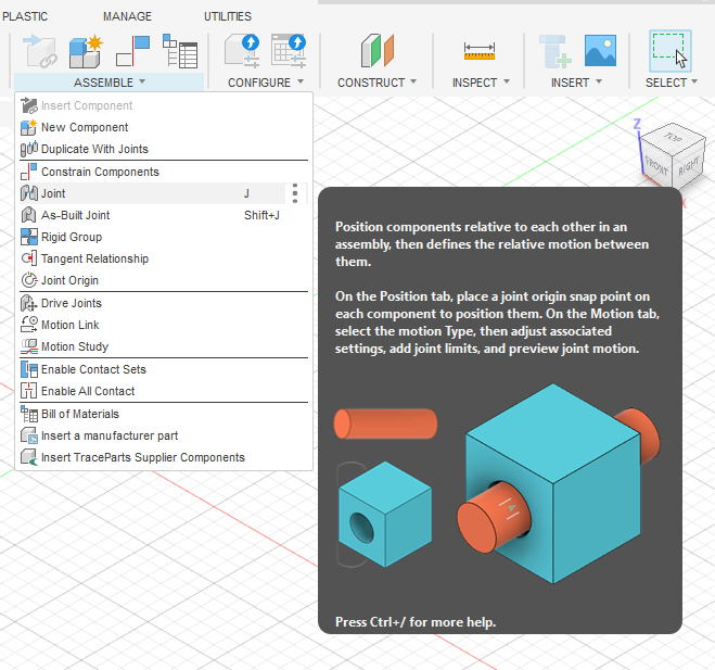
The Heart of the Assembly: Mastering Fusion 360 Joints
If components are the bones of your assembly, Fusion 360 joints are the ligaments and tendons that define how they move. This is one area where Fusion 360 differs significantly from older CAD systems that rely on complex mates and constraints.
A joint in Fusion 360 works by defining motion, not by restricting it. When you apply a joint between two components, you are essentially removing all six degrees of freedom (three translational, three rotational) and then adding back only the specific motion you want.
Understanding the 7 Types of Joints
Fusion 360 provides seven distinct types of joints to define any mechanical relationship you can imagine.
- Rigid: This is the most common joint. It locks two components together, removing all degrees of freedom. Think of a welded or glued connection.
- Revolute: Allows pure rotational motion around a single defined axis. This is your go-to for hinges, wheels, and axles.
- Slider: Allows pure linear motion along a single axis. Perfect for pistons or parts moving in a track.
- Cylindrical: A combination of Revolute and Slider. It allows a component to rotate around an axis and slide along it simultaneously. Think of a shaft in a sleeve.
- Pin-Slot: Allows a component to rotate around one axis and translate along a different axis. Imagine a pin moving in a straight slot.
- Planar: Constrains a component to move on a 2D plane. It can translate in two directions and rotate about the axis normal to the plane.
- Ball: Allows rotation around all three axes (X, Y, and Z) from a single pivot point. This is the joint for a ball-and-socket mechanism, like a joystick or a spherical rod end.
Joints vs. As-Built Joints: What’s the Difference?
This is a common point of confusion for new users. The key difference is your workflow. Answering understanding joints vs as-built joints in Fusion 360 is simple:
- Standard Joint: You use the ‘Joint’ command when your components are not yet in their correct positions. Fusion 360 will ask you to select a connection point on each component, and then it will snap them into place and apply the joint motion simultaneously.
- As-Built Joint: You use the ‘As-Built Joint’ command when your components have already been modeled in their final, assembled positions (a common scenario in top-down design). The components don’t move; you simply select them and define the relative motion that should exist between them.
A Step-by-Step Guide: How to Create an Assembly in Fusion 360
Let’s walk through the fundamental process of creating a basic assembly. We’ll model a simple hinged plate.
Step 1: Setting Up Your Design & Creating the Base Component
- Open a new, empty design.
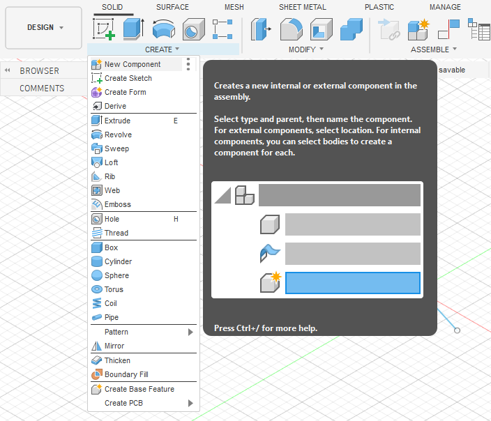
- Before you sketch anything, go to
Create > New Component. Name it ‘Base Plate’. - Now, with the ‘Base Plate’ component activated, create a sketch for your base. Extrude it to give it thickness.
- This first component needs to be fixed in space. Right-click the ‘Base Plate’ component in the browser tree and select ‘Ground’. This locks it down and removes all of its degrees of freedom.
Step 2: Creating the Second Component
- Activate the top-level assembly in the browser tree.
- Go to
Create > New Componentagain. Name this one ‘Hinge Plate’. - Create a sketch for the hinge plate. You can project geometry from the ‘Base Plate’ to ensure everything lines up perfectly. Extrude it.
Step 3: Applying a Revolute Joint
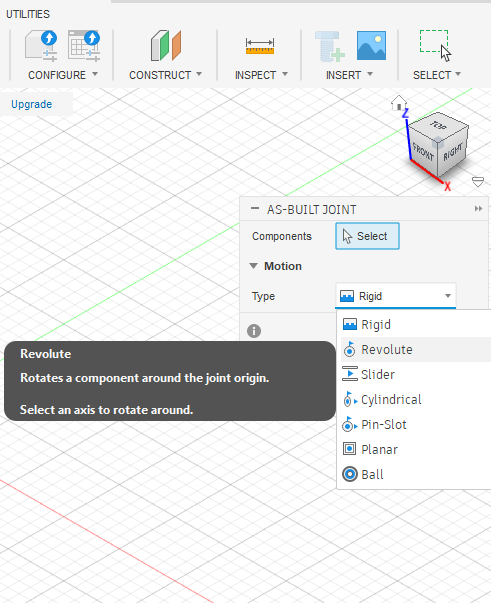
- Since the parts are already in position, we’ll use an As-Built Joint. Go to
Assemble > As-Built Joint. - Change the Joint Type in the dialog box to ‘Revolute’.
- Select the ‘Hinge Plate’ and then the ‘Base Plate’ as your components.
- For the ‘Position’, you need to define the axis of rotation. Select the circular edge of the hinge pin hole.
- Click ‘OK’. The joint is now created.
Step 4: Testing the Motion
- Click and drag the ‘Hinge Plate’. It should now rotate around the axis you defined, just like a real hinge. The ‘Base Plate’ will remain stationary because it is grounded.
- You can further refine this by right-clicking the joint in the browser, selecting ‘Edit Joint Limits’, and defining minimum and maximum angles of rotation to prevent it from moving through the base.
Advanced Techniques and Best Practices
Once you’ve mastered the basics, you can start incorporating more advanced strategies into your workflow, especially when dealing with complex projects.
Best Practices for Large Assemblies in Fusion 360
Performance can become a challenge with assemblies containing hundreds or thousands of parts. Here are some key strategies:
- Use External Components: As mentioned, linking to external files is crucial. It keeps your main assembly file size down and allows for better organization. This is a core tenant of good CAD data management.
- Simplify Components: For complex purchased parts like motors or electronics, use simplified versions in your main assembly. You don’t need every internal wire and fillet to check for fit and motion.
- Use Rigid Groups: If you have a set of components that are bolted or welded together and don’t move relative to each other (like a motor and its mounting bracket), use the
Assemble > Rigid Groupcommand. This treats them as a single entity for calculation purposes, significantly reducing computational load. - Control Visibility: Turn off the visibility for components you aren’t currently working with.
Simulating Motion with a Motion Study
A motion study is a powerful tool for visualizing and analyzing the kinematics of your assembly. You can find it under the Assemble menu.
With a motion study, you can select any joint in your model and specify its movement over a series of steps. For example, you can command a Revolute joint to rotate 360 degrees in 100 steps. When you play the animation, you’ll see your assembly move, and all other components linked by joints will react accordingly. This is invaluable for checking for interference, verifying mechanical advantage, and creating compelling presentations of your design. For a deeper dive into mechanical principles, resources like MIT OpenCourseWare can provide excellent theoretical backing.
Generating a Bill of Materials (BOM)
One of the most practical outputs of a well-made assembly is the bill of materials (BOM). Fusion 360 can automatically generate a parts list from your assembly. Simply go to the Tables menu and select Table. Fusion 360 will create a table listing every component, its quantity, part number, description, and more. This is essential for costing, purchasing, and manufacturing documentation. You can learn more about the specifics directly from the Autodesk Knowledge Network.
Common Pitfalls to Avoid in Fusion 360 Assemblies
As you learn, you’ll likely encounter a few common roadblocks. Here’s how to steer clear of them:
- Forgetting to Create Components: This is the #1 mistake. If you model everything as bodies in the root design, you’ll have to do significant rework to turn it into a functional assembly.
- Not Grounding the Base Component: An ungrounded assembly will float freely in space. When you try to move one part, the whole thing might move, which is not helpful. Always ground one component to serve as your anchor.
- Applying Redundant Joints: If a component is already fully constrained by a set of joints, adding another one will cause an error. Always think about the simplest joint that can achieve the desired motion.
- Fighting with the Timeline: In a large top-down assembly, the timeline can become a beast. Use feature grouping, naming, and good organization from the start to keep it manageable.
Conclusion: Your Journey to Assembly Mastery
Mastering Fusion 360 assemblies is a transformative step in your design journey. It elevates you from creating simple objects to engineering sophisticated systems. We’ve covered the critical building blocks: the absolute necessity of Fusion 360 components, the strategic choice between top-down and bottom-up design, and the pivotal role of Fusion 360 joints in defining motion.
By following the step-by-step guide, embracing advanced techniques like motion studies, and avoiding common pitfalls, you are now equipped to build with confidence. Remember that every complex machine is just a collection of simpler parts working together. With the power of Fusion 360’s assembly environment, you now have the tools to define those relationships and bring your most ambitious ideas to life.