
Introduction
Sketching is the foundation of all CAD modeling—it’s where ideas begin, shapes take form, and dimensions define precision. In Autodesk Fusion 360, sketches are primarily 2D by default, created on planar surfaces or construction planes. However, many real-world designs require non-planar geometry, paths, and curves that cannot be confined to a single plane. That’s where 3D Sketching comes into play.
A 3D Sketch in Fusion 360 allows you to draw geometry in three dimensions simultaneously, freeing you from the limitations of flat planes. It’s essential for creating complex sweeps, wireframes, tubing paths, surface lofts, and multi-axis features.
In this guide, we’ll explore everything you need to know about 3D Sketching in Fusion 360—from the basics of enabling it, to advanced workflows, constraints, and real-world use cases.
Table of Contents
1. Understanding Sketching in Fusion 360
Before diving into 3D sketches, let’s recap how sketching works in Fusion 360:
- 2D Sketch: By default, sketches are created on a plane (XY, XZ, or YZ). You draw geometry like lines, arcs, circles, and rectangles. These are then used to create 3D features (extrudes, revolves, sweeps, etc.).
- 3D Sketch: A mode that allows sketch entities to exist in all three spatial dimensions (X, Y, and Z) simultaneously. You’re not confined to a single flat plane.
While 2D sketches are perfect for most parametric modeling, 3D sketches are crucial for modeling pipes, cables, guide paths, rails, organic frames, and other freeform structures.
2. What Is a Fusion 360 3D Sketch ?
A 3D Sketch is a special sketching environment that allows you to create geometry anywhere in 3D space.
In 3D Sketch mode:
- You can create and manipulate sketch entities in multiple planes simultaneously.
- Lines, splines, and arcs can be oriented in 3D space instead of lying flat.
- Sketch points can exist outside a specific sketch plane.
- Constraints and dimensions work across three axes.
Fusion 360 introduced full 3D Sketch support as part of its continuous updates, enabling greater flexibility for design and manufacturing workflows.
3. Enabling 3D Sketch Mode
3D Sketching isn’t turned on by default. To enable it:
Steps to Activate 3D Sketch Mode:
- Open a new design or existing model.
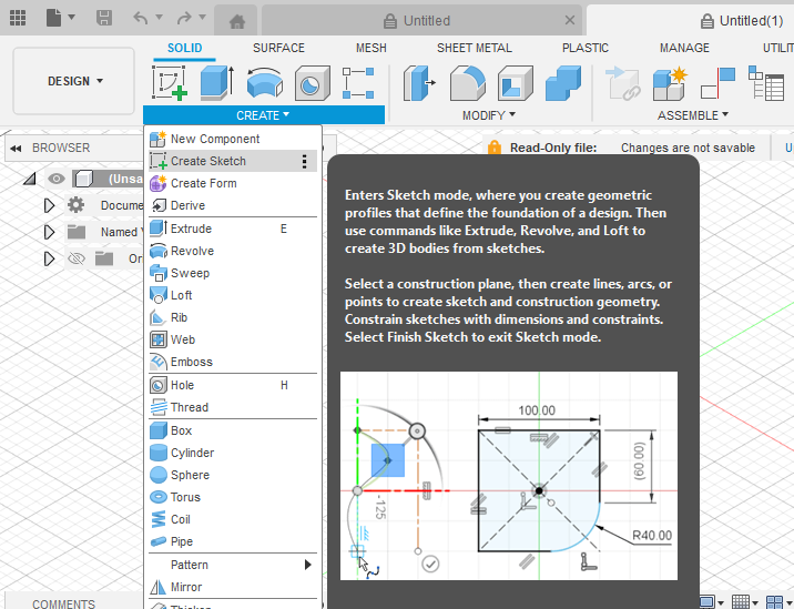
- Go to Create → Create Sketch.
- Choose any initial plane (e.g., XY).
- In the Sketch Palette, scroll down and toggle ON “3D Sketch”.
Once activated, any new geometry you create can extend out of the 2D plane into 3D space.
💡 Tip: You can toggle 3D Sketch on or off anytime, even within the same sketch, to switch between 2D and 3D modes.
4. 3D Sketch Tools and Entities
Fusion 360 supports a wide range of entities in 3D sketches.
Common 3D Sketch Tools:
- Line – Create 3D lines by selecting start and end points in space.
- Arc / Circle – Draw arcs and circles with true 3D orientation.
- Spline (Fit Point or Control Point) – Create freeform 3D curves.
- Point – Place reference points anywhere in 3D.
- Project / Include – Include edges, faces, or geometry from 3D models.
- Construction Lines – Guide 3D sketches for alignment and positioning.
Fusion 360 uses 3D cursor navigation—the orientation of the triad and active work plane defines the direction of the next segment.
5. Navigating and Drawing in 3D Space
3D sketching can feel disorienting at first because you’re no longer confined to a flat grid. Here are some navigation tips:
Techniques:
- Use ViewCube: Rotate your view often (Home view, Front, Right, etc.) to understand spatial relationships.
- Use the Shift + Middle Mouse Button: Orbit around geometry while sketching.
- Use XYZ Direction Inputs: When creating lines, enter values in X, Y, Z to define precise 3D coordinates.
- Snap to Points and Faces: Hover over edges or corners to automatically align sketch entities.
6. Applying 3D Constraints and Dimensions
Fusion 360 supports many geometric constraints in 3D sketches, similar to 2D sketches.
Common Constraints:
- Coincident – Make points lie on lines or other points in 3D.
- Collinear – Align multiple lines in 3D.
- Perpendicular / Parallel – Define 3D orientation between entities.
- Tangent – Ensure smooth transitions for curves.
- Equal – Keep lengths consistent across lines or arcs.
3D Dimensions:
When dimensioning in 3D:
- Use Smart Dimension Tool (D key).
- Click two points to create a linear dimension between them (3D distance).
- Use angular dimensions for 3D angles.
Fusion 360 visualizes 3D dimensions clearly with reference lines across axes.
7. Using Construction Geometry
Construction geometry is essential in 3D sketches for creating frameworks.
Examples:
- Use construction lines to represent axes or guides.
- Use reference points for defining start or end of paths.
- Define planes at angles or offsets to control 3D positioning.
Combining construction geometry with standard lines gives precise spatial control.
8. Creating 3D Sketch Paths for Features
One of the most common uses of 3D sketches is to define paths for sweeps, pipes, and lofts.
Example: Create a 3D Pipe
- Enable 3D Sketch.
- Use Line / Arc tools to define a pipe path with bends.
- Finish sketch.
- Create a profile circle on a perpendicular plane.
- Use Create → Sweep.
- Select the profile and 3D sketch path.
✅ Result: A fully 3D pipe with smooth bends following your 3D sketch path.
9. Projecting Geometry into 3D Sketch
Often you need to reference existing geometry—edges, faces, or points—inside a 3D sketch.
Steps:
- Activate your 3D sketch.
- Use Project → Include → 3D Geometry.
- Select edges, vertices, or bodies.
- They will appear as reference geometry inside the 3D sketch.
This is especially useful for creating guide curves for lofts or sweeps.
10. Creating 3D Splines and Curves
3D Splines are one of the most powerful tools in Fusion 360 for modeling organic and freeform geometry.
Steps to Create a 3D Spline:
- Start a 3D Sketch.
- Select Spline (Fit Point).
- Click points in different planes (Z, X, Y) to define the curve.
- Adjust control handles or move points for curvature control.
Applications:
- Wire harness routing.
- Airflow duct paths.
- Aesthetic surfaces for product design.
11. Combining 2D and 3D Sketches
You can mix both 2D and 3D sketches in the same model.
Example:
- Create a 2D sketch on a plane for a base shape.
- Finish the sketch.
- Create a 3D sketch to add non-planar paths (e.g., sweeps or rails).
- Combine them using lofts, sweeps, or guide surfaces.
This hybrid approach keeps parametric control while allowing design freedom.
12. 3D Sketch for Surface Modeling
In Surface Modeling, 3D sketches act as guide curves and boundaries.
Workflow Example:
- Create 3D sketch paths for the edges of a surface.
- Use Loft or Sweep Surface tools.
- Define multiple guide curves to control shape.
Surfaces generated from 3D sketches can be further thickened or trimmed for complex design features.
13. Using 3D Sketch in Assemblies
3D sketches are also useful in assembly design.
Example Applications:
- Define wire harness paths connecting components.
- Create motion paths for moving parts.
- Build frame skeletons for structural assemblies.
You can create a 3D sketch in a separate component and reference it across the assembly.
14. Advanced Techniques
1. Using 3D Constraints with Reference Planes
Create angled planes, then constrain 3D sketch geometry to intersect or align with them.
2. Convert 2D Sketches to 3D
You can “lift” parts of a 2D sketch into 3D by moving points or segments using the Move (M) command along the Z-axis.
3. Combining 3D Sketch with Parameters
Apply user parameters (e.g., pipe length, bend radius) to control 3D sketch geometry dynamically.
4. Creating Frame Structures
Fusion 360’s Frame Generator (Design Workspace) can use 3D sketches as skeleton references for beams and profiles.
15. Troubleshooting 3D Sketch Issues
| Issue | Possible Cause | Solution |
|---|---|---|
| Entities not appearing as expected | 3D sketch mode is off | Turn on “3D Sketch” in the Sketch Palette |
| Constraints behaving unpredictably | Over-constrained geometry | Remove redundant constraints |
| Can’t select points in 3D | Working from limited view angle | Rotate the view or switch to orthographic |
| Misaligned geometry | Incorrect coordinate input | Check X/Y/Z direction during creation |
16. Tips for Efficient 3D Sketching
- Use construction geometry generously to define framework and orientation.
- Label sketches clearly – 3D sketches can get complex fast.
- Work in stages – Build small, controlled sections.
- Use constraints sparingly – Too many 3D constraints can overdefine your model.
- Keep view dynamic – Rotate frequently to ensure correct depth perception.
- Use parameters for controlled, adjustable dimensions.
17. Real-World Applications
1. Pipe and Tube Routing
3D sketches define centerlines for sweeps that become pipes, conduits, or hydraulic tubes.
2. Frame and Structure Design
3D sketches serve as skeletons for frame members, trusses, and lattice structures.
3. Cable and Wire Harness Design
Use splines in 3D sketches to model realistic wire harness paths.
4. Aerospace and Automotive Surfaces
Complex body panels, ducting systems, and aerodynamic surfaces rely heavily on 3D guide sketches.
5. Product Design
Designers use 3D sketches to create organic transitions and ergonomic surfaces.
18. Limitations of Fusion 360 3D Sketch
While powerful, 3D Sketching in Fusion 360 has some limitations:
- No “auto-plane detection” like some other CAD systems.
- Limited constraint visibility in complex 3D environments.
- Slightly slower performance in large assemblies.
- Fewer dedicated 3D spline manipulation tools than in high-end surfacing software like Alias or CATIA.
Still, for most design and engineering workflows, Fusion 360’s 3D Sketch functionality is more than sufficient.
19. Future Enhancements (Fusion 360 Roadmap Insight)
Autodesk continuously enhances 3D sketching capabilities. Expected improvements include:
- Better constraint visualization in 3D space.
- Enhanced control for curvature and tangent handles.
- Automatic snapping to 3D model edges or surfaces.
- Improved performance for large 3D spline networks.
Conclusion
3D Sketching in Fusion 360 is an essential tool for advanced CAD modeling, enabling designers and engineers to move beyond the limitations of 2D planes. Whether you’re creating pipe routes, complex surfaces, or mechanical frames, 3D sketches give you the flexibility to define geometry anywhere in space.
Key takeaways:
- Enable “3D Sketch” in the Sketch Palette to start sketching in 3D.
- Use lines, arcs, and splines to build non-planar paths.
- Apply 3D constraints and dimensions to control geometry precisely.
- Combine 2D and 3D sketches for flexible hybrid workflows.
- Use 3D sketches as guides for sweeps, lofts, and surfaces.
By mastering 3D Sketching in Fusion 360, you unlock the ability to design truly spatial, complex, and creative models, bridging the gap between engineering precision and design freedom.