

Introduction
AutoCAD UCS (User Coordinate System) is an essential feature that allows users to define and manipulate custom coordinate systems within their drawings. While AutoCAD’s default World Coordinate System (WCS) provides a fixed reference for all objects, the UCS offers flexibility in 3D modeling, allowing users to align the coordinate system with specific geometry, view angles, or design needs. This guide will explain the fundamentals of the UCS in AutoCAD, how to create and manage custom UCS settings, and how to use the UCS to enhance your 2D drafting and 3D modeling workflows.
What is the User Coordinate System (UCS) in AutoCAD?
The User Coordinate System (UCS) in AutoCAD is a movable Cartesian coordinate system that can be aligned to any part of your drawing. By default, AutoCAD uses the World Coordinate System (WCS), where the X, Y, and Z axes are fixed. The UCS allows you to redefine the orientation of these axes, making it easier to work with objects that are not aligned with the default coordinate system.
This feature is particularly useful in 3D modeling, where objects may need to be viewed, edited, or constructed from different angles. By adjusting the UCS, you can ensure that the coordinate system is aligned with your design, simplifying tasks like drawing, editing, and measuring.
Understanding the Basics of AutoCAD UCS
World Coordinate System (WCS) vs. User Coordinate System (UCS)
- World Coordinate System (WCS): The WCS is the default, fixed coordinate system in AutoCAD. It provides a universal reference point where the X-axis is horizontal, the Y-axis is vertical, and the Z-axis extends outward. All objects are created and measured relative to the WCS unless a UCS is applied.
- User Coordinate System (UCS): The UCS is a flexible, user-defined coordinate system that can be oriented to suit specific parts of your drawing. The UCS can be rotated, tilted, or aligned to any geometry, allowing for more precise control over drawing and editing in both 2D and 3D spaces.
Also Read – Best Mouse for CAD
The UCS Icon
The UCS icon represents the orientation of the current UCS in the drawing area. It shows the direction of the X, Y, and Z axes and updates in real-time as you adjust the UCS. Understanding the UCS icon is crucial for visualizing the orientation of your coordinate system and ensuring that you are working in the correct plane.
Key UCS Commands in AutoCAD
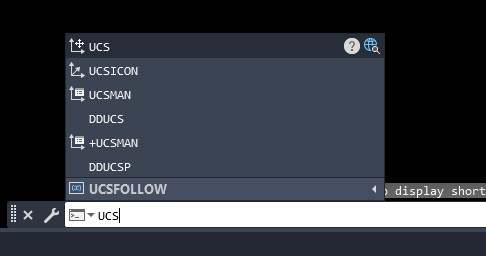
- UCS: The primary command for creating and managing User Coordinate Systems. This command allows you to set a new UCS based on specific criteria such as object alignment, face, view, or by entering coordinate values directly.
- UCSICON: Controls the visibility and placement of the UCS icon in the drawing area. This command can be used to turn the UCS icon on or off or to change its display settings.
- PLAN: Aligns the view of the drawing area to the current UCS, making the XY plane of the UCS the primary view. This command is useful for working in a newly defined UCS.
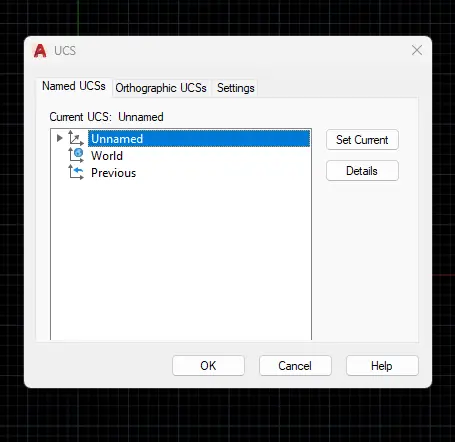
- UCSMAN: Opens the UCS Manager, which provides a graphical interface for managing multiple UCS settings, including saving, restoring, and deleting UCS configurations.
Creating and Managing UCS
Creating a New UCS
Creating a new UCS allows you to customize the coordinate system for specific tasks or views. Here’s how to create a UCS:
- Using Object: Align the UCS to a specific object:
- Type
UCSand press Enter. - Type
OB(short for Object) and press Enter. - Select the object you want to align the UCS with. AutoCAD will automatically align the UCS based on the selected object’s orientation.
- Type
- Using Face: Align the UCS to a face on a 3D solid:
- Type
UCSand press Enter. - Type
FACEand press Enter. - Select the face on the 3D solid you want the UCS to align with. The UCS will be reoriented to match the face.
- Type
- Using View: Align the UCS to the current view direction:
- Type
UCSand press Enter. - Type
VIEWand press Enter. The UCS will align with the view direction, making it easier to work in perspective views.
- Type
- Manual Definition: Define the UCS manually using points:
- Type
UCSand press Enter. - Specify the origin point (0,0,0) of the UCS.
- Specify a point on the positive X-axis.
- Specify a point on the positive Y-axis. The UCS will be created based on these points.
- Type
Managing Multiple UCS Configurations
AutoCAD allows you to create and manage multiple UCS configurations, which can be saved and restored as needed:
- Saving a UCS:
- After creating a UCS, you can save it for future use by typing
UCSand pressing Enter. - Type
S(for Save) and press Enter. - Enter a name for your UCS and press Enter. The UCS is now saved and can be accessed anytime.
- After creating a UCS, you can save it for future use by typing
- Restoring a UCS:
- To restore a saved UCS, type
UCSand press Enter. - Type
R(for Restore) and press Enter. - Select the saved UCS from the list by typing its name or selecting it from the UCS Manager.
- To restore a saved UCS, type
- Switching Between UCS Configurations:
- Use the UCS Manager (
UCSMAN) to switch between different UCS configurations. This tool provides a graphical interface for selecting, activating, and managing multiple UCS settings.
- Use the UCS Manager (
- Deleting a UCS:
- If a UCS is no longer needed, you can delete it by typing
UCSand pressing Enter. - Type
D(for Delete) and press Enter. - Select the UCS you want to delete from the list.
- If a UCS is no longer needed, you can delete it by typing
Using the UCS in 2D Drafting and 3D Modeling
Applying UCS in 2D Drafting
In 2D drafting, the UCS can be used to align your coordinate system with angled or rotated parts of your drawing. This allows for more precise placement of objects relative to specific geometry:
- Aligning UCS with an Object: If you need to draw or edit objects along an angled line or feature, align the UCS to that object using the
UCS>OBcommand. This simplifies the drawing process by aligning the coordinate system with the desired angle. - Rotating the UCS for Angled Drawing: If your drawing includes elements that are not aligned with the default WCS, you can rotate the UCS to match the angle of these elements. This can be done by specifying a new UCS origin and rotation angle.
Using UCS in 3D Modeling
The UCS is particularly powerful in 3D modeling, where objects often need to be manipulated in three dimensions:
- Aligning UCS to 3D Faces: When working with complex 3D models, align the UCS to specific faces of a solid using the
UCS>FACEcommand. This makes it easier to draw, edit, or measure features on that face. - Working in Different Planes: The UCS allows you to switch between different planes of your model (XY, YZ, ZX) by defining the UCS accordingly. This flexibility simplifies the process of constructing 3D objects from different angles.
- Creating UCS for Isometric Views: For isometric drawings, you can set the UCS to one of the isometric planes (Top, Right, or Left) using the
UCS>3POINTcommand. This sets up the UCS for drawing isometric views that align with the standard isometric axes.
Tips for Efficient UCS Management
- Naming Conventions: Use descriptive names when saving UCS configurations, such as “Front_Face” or “Isometric_Top.” This makes it easier to identify and restore the correct UCS when needed.
- Plan View Reset: After working in a custom UCS, you may want to return to the default WCS view. Use the
PLAN>WORLDcommand to reset the view to the WCS and align the UCS accordingly. - Using UCS History: AutoCAD remembers the last few UCS settings used. You can cycle through recent UCS configurations by typing
UCSand using the arrow keys to select a previous UCS from the history list.
Suggested- How to set coordinate system in AutoCAD
Conclusion
The User Coordinate System (UCS) in AutoCAD is a powerful feature that enhances flexibility and precision in both 2D drafting and 3D modeling. By allowing you to define custom coordinate systems, the UCS enables you to work more efficiently on complex designs, aligning the drawing environment with your specific needs. Whether you are aligning objects, working on different planes, or managing multiple UCS configurations, mastering the UCS will greatly improve your workflow and productivity in AutoCAD.
FAQs
- How do I switch back to the default coordinate system in AutoCAD?
You can switch back to the default World Coordinate System (WCS) by typingUCSand selecting “World” or by typingPLANand thenWORLDto reset the view. - Can I save multiple UCS configurations?
Yes, you can save multiple UCS configurations using theUCS>S(Save) command. Each saved UCS can be named and restored as needed. - What is the difference between UCS and WCS?
The World Coordinate System (WCS) is the fixed, default coordinate system in AutoCAD. The User Coordinate System (UCS) is a flexible, user-defined system that can be customized to align with specific parts of your drawing. - How do I align the UCS with an angled object?
You can align the UCS with an angled object by using theUCS>OB(Object) command. Select the object, and the UCS will align with its orientation. - How do I rotate the UCS in AutoCAD?
You can rotate the UCS by specifying new origin points or by using theUCS>3POINTcommand to set the UCS based on three points in your drawing