

Introduction
AutoCAD is a powerful tool not only for architectural and mechanical designs but also for electrical schematics and circuit layouts. Electrical drawings rely on standardized symbols to represent different components in the system, ensuring consistency, clarity, and ease of communication between engineers, electricians, and contractors. This article provides an overview of the standard AutoCAD electrical symbols and explains how to effectively integrate them into your designs. Whether you’re working on wiring diagrams, circuit layouts, or industrial control systems, mastering these symbols is crucial for creating precise and professional electrical designs.
Table of Contents
What Are Electrical Symbols in AutoCAD?
Electrical symbols in AutoCAD represent components such as switches, outlets, lights, transformers, and conductors in electrical systems. These symbols follow industry standards such as IEC (International Electrotechnical Commission), ANSI (American National Standards Institute), and IEEE (Institute of Electrical and Electronics Engineers). By using these standardized symbols, engineers and electricians can interpret electrical drawings accurately, regardless of their location or industry.
Electrical symbols typically represent:
- Power Sources: Batteries, power supplies, and transformers.
- Switches: Toggle switches, push buttons, circuit breakers.
- Outlets: Power outlets, receptacles, GFCI outlets.
- Lighting: Ceiling lights, spotlights, emergency lighting.
- Wiring and Conductors: Lines representing wires, with labels for connections and junctions.
- Grounding: Earth grounding symbols for safety and protection circuits.
- Electrical Devices: Motors, relays, contactors, and sensors.
Why Are Standard Electrical Symbols Important?
Using standardized electrical symbols is essential for ensuring clarity and consistency in electrical design. When a designer follows these symbols, it becomes easier for others to read and implement the drawing without confusion. Furthermore, using standard symbols ensures that the designs comply with local electrical codes and international standards, reducing the risk of errors and ensuring safety.
Common AutoCAD Electrical Symbols
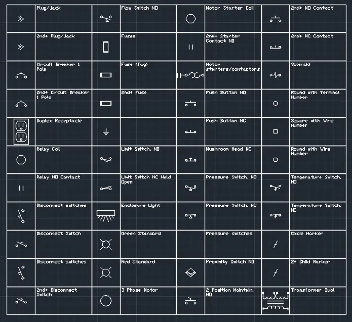
Here’s a breakdown of the most commonly used electrical symbols in AutoCAD, grouped by category:
Power Supply Symbols
- Battery: A standard battery symbol consists of a series of alternating short and long lines, representing positive and negative terminals.
- Example Symbol: Two parallel lines, with one longer than the other, indicate the positive and negative terminals.
- AC Power Supply: Represented by a circle with a sine wave inside, indicating alternating current.
- Example Symbol: A simple sine wave inside a circle, showing that the power is alternating current (AC).
- DC Power Supply: A direct current (DC) power supply is shown as a line with positive (+) and negative (-) symbols.
- Example Symbol: A horizontal line with a “+” and “-” sign indicating polarity.
Switches and Circuit Protection
- Single Pole Switch: A simple break in the circuit line with a dot at each end, representing a switch that can open or close the circuit.
- Example Symbol: A diagonal line intersecting a circuit line, representing a toggle switch.
- Circuit Breaker: A break in the circuit with an arc drawn over it, symbolizing a device that interrupts the flow of current when overloaded.
- Example Symbol: A break in the line with an arched line over it, indicating a circuit breaker.
- Push Button: Shown as a circle with a line inside, indicating a button that can be pressed to activate or deactivate a circuit.
- Example Symbol: A circle with a horizontal line through it, representing a simple push-button switch.
Outlets and Receptacles
- Duplex Outlet: Represented by two parallel lines or circles within a rectangular box, indicating a standard electrical outlet.
- Example Symbol: A small rectangle with two vertical lines inside, showing a typical power outlet.
- GFCI Outlet: Similar to a duplex outlet symbol but with the addition of a “T” or “GFCI” label, indicating a Ground Fault Circuit Interrupter outlet.
- Example Symbol: A rectangle with two lines and a “T” or “GFCI” label next to it.
Lighting Symbols
- Ceiling Light: A circle with an “X” inside, representing a standard ceiling light fixture.
- Example Symbol: A small circle with an “X” inside, indicating a ceiling light.
- Recessed Lighting: A circle with a line through it, showing recessed or flush-mounted lighting.
- Example Symbol: A circle with a diagonal line through it, representing recessed lighting.
- Emergency Light: A small rectangle with a light bulb symbol inside, often used in safety and emergency lighting plans.
- Example Symbol: A small square or rectangle with a bulb inside, representing emergency lighting.
Grounding Symbols
- Earth Ground: Represented by a series of horizontal lines of decreasing width, indicating the grounding of a circuit for safety.
- Example Symbol: Three horizontal lines, with the top one being the longest, showing a ground connection.
- Chassis Ground: Similar to the earth ground symbol but with a triangular shape added, indicating grounding to a metal chassis or enclosure.
- Example Symbol: A triangle with horizontal lines underneath, indicating a chassis ground.
Wiring and Connections
- Wiring Line: A simple straight line represents a wire or conductor. Multiple lines can be used to represent complex wiring systems, with labels indicating wire types and sizes.
- Example Symbol: A straight line connecting two symbols, representing a standard electrical wire.
- Connection Junction: A dot where multiple lines intersect, indicating an electrical connection point between wires.
- Example Symbol: A small dot at the intersection of two or more lines, indicating that the wires are connected.
- No Connection: An arc drawn over the intersection of lines indicates that no connection exists between the wires.
- Example Symbol: A small arch over the point where two lines cross, showing no electrical connection.
Motors and Devices
- Motor: Represented by a circle with the letter “M” inside, indicating an electric motor in a system.
- Example Symbol: A circle with an “M” inside, representing a motor in the circuit.
- Relay: A rectangle or box with contacts shown inside, representing an electromechanical relay in a circuit.
- Example Symbol: A rectangle with lines representing the relay’s contacts, showing how the relay is connected in the system.
- Resistor: A zigzag line representing a resistor used to limit the flow of electrical current.
- Example Symbol: A jagged or zigzag line in the circuit path, representing a resistor.
How to Use Electrical Symbols in AutoCAD
Using electrical symbols effectively in AutoCAD requires understanding the symbols and knowing how to incorporate them into your designs. Here’s a step-by-step guide on how to use them in your electrical schematics:
Step 1: Accessing Electrical Symbols
- Open AutoCAD Electrical: If you are using AutoCAD Electrical (a specialized version of AutoCAD for electrical design), you’ll have access to built-in libraries of electrical symbols that comply with various industry standards.
- Go to the Electrical tab in the Ribbon, where you’ll find predefined symbols for power, switches, lighting, and more.
- Insert Symbols from the Library: Use the Symbol Library to insert standard electrical symbols into your drawing. You can search for specific symbols like “switch” or “outlet” to quickly find what you need.
- Type
INSERTin the Command Line to access the block insertion menu, then browse through the electrical symbol library to find the appropriate symbol.
- Type
Step 2: Placing Symbols in the Design
- Draw the Circuit Layout: Before placing symbols, draw the circuit wiring using lines to represent wires and conductors. This creates a clear framework for placing electrical components.
- Insert Symbols: Once the wiring is in place, insert symbols by selecting the component from the library and placing it directly on the wire or circuit. For example, place a switch symbol at the point where you want to control the flow of current in the circuit.
- Use Object Snaps (OSNAP): Activate
OSNAPto precisely place symbols at key points like the intersection of wires or junctions. This ensures accurate alignment and connection of components in the circuit.
Step 3: Labeling and Annotating
- Add Labels to Symbols: Use the
TEXTorMTEXTcommands to add descriptive labels to each symbol, such as “Light Switch,” “120V Outlet,” or “Circuit Breaker.” - Wire Numbering and Tagging: AutoCAD Electrical can automatically assign wire numbers and tags to help identify different connections and components in a large system. Use the Wire Tagging feature to generate wire numbers and device tags for easy identification.
- Adding Dimensions and Notes: For more complex layouts, add dimensions using the
DIMLINEARcommand to indicate the distances between components. Notes can also be added to clarify installation or wiring instructions.
Step 4: Organizing the Drawing with Layers
- Create Layers for Electrical Systems: Use layers to organize different parts of the electrical system, such as power circuits, lighting, control systems, and grounding. This keeps the drawing clean and makes it easier to modify or isolate certain components.
- Example layers: Power_Wiring, Lighting_Circuit, Grounding, Annotations.
- Color Coding Layers: Assign different colors to layers to visually differentiate between systems. For instance, use red for power circuits, blue for lighting, and green for grounding.
Step 5: Verifying and Finalizing the Design
- Run Electrical Checks: AutoCAD Electrical includes design verification tools to check for errors such as unconnected wires, missing components, or duplicate tags. Run these checks to ensure your design is complete and error-free.
- Print or Export the Design: Once the electrical schematic is complete, you can print it or export it as a PDF or DWG file to share with engineers, electricians, or contractors.
Best Practices for Using Electrical Symbols in AutoCAD
- Use Standardized Symbols: Always use standardized electrical symbols (IEC, ANSI, or IEEE) to ensure that your drawings are universally understood and compliant with industry regulations.
- Maintain Consistent Annotations: Keep labeling and tagging consistent across all drawings. This is especially important in large projects with many electrical components.
- Organize with Layers: Use layers to separate different circuits and systems. This makes it easier to manage large electrical schematics and troubleshoot specific sections of the design.
- Regularly Save and Audit Drawings: Save your progress frequently and use AutoCAD’s auditing tools to check for errors or potential issues in your design, such as incomplete circuits or missing connections.
Conclusion
AutoCAD is an invaluable tool for electrical design, offering a vast library of standard electrical symbols that streamline the creation of wiring diagrams, circuit layouts, and electrical schematics. By mastering these symbols and learning how to apply them effectively in your designs, you can produce clear, detailed, and professional electrical drawings that meet industry standards. Whether you’re working on residential wiring plans, industrial control systems, or large-scale electrical grids, understanding how to use AutoCAD’s electrical symbols is essential for any electrical engineer or designer.
FAQs
- How do I insert electrical symbols in AutoCAD?
You can insert electrical symbols from the Symbol Library in AutoCAD Electrical or by using pre-made blocks in standard AutoCAD. Use theINSERTcommand to place them in your drawing. - What is the best way to organize electrical drawings in AutoCAD?
Use layers to separate different systems (e.g., power, lighting, grounding). Color coding layers and using consistent symbols helps maintain clarity and organization. - What are the common electrical symbols used in AutoCAD?
Common symbols include switches, outlets, circuit breakers, light fixtures, motors, resistors, and grounding symbols. These are standardized for easy interpretation. - Can AutoCAD automatically tag wires and components?
Yes, AutoCAD Electrical can automatically assign wire numbers, device tags, and circuit labels using the built-in wire tagging and numbering tools. - How do I ensure that my electrical design meets industry standards?
Use standardized symbols (IEC, ANSI, or IEEE) and follow local electrical codes when designing electrical schematics. AutoCAD Electrical also includes verification tools to check for compliance.