
Introduction
AutoCAD is a powerful tool widely used in architecture, engineering, and design for creating detailed 2D and 3D drawings. At the heart of this software are its commands—specific instructions that allow users to perform a vast range of tasks, from drawing basic shapes to creating complex 3D models. Understanding and mastering these commands is essential for anyone looking to enhance their productivity and efficiency in AutoCAD. This article provides a comprehensive breakdown of the most important AutoCAD commands, exploring their functions and how they can be used to streamline your design process.
Table of Contents
Understanding AutoCAD Commands
AutoCAD commands are instructions typed into the Command Line or selected from the Ribbon and toolbars. These commands tell the software what action to perform, whether it’s drawing a line, rotating a shape, or adding text to a drawing. The Command Line interface remains a favorite among many seasoned AutoCAD users due to its speed and precision. Although AutoCAD’s graphical user interface has become more user-friendly over the years, knowing the right commands can significantly enhance your workflow.
Basic Drawing Commands
LINE (L)
The LINE command is one of the most fundamental in AutoCAD. It allows you to draw straight lines between two points. By typing “L” in the Command Line and specifying the start and end points, you can create precise lines that form the basis of more complex shapes and drawings.
CIRCLE (C)
The CIRCLE command is used to draw circles. You can specify the center point and radius or diameter to create a circle of any size. This command is essential for creating circular elements in your design, such as holes, arcs, and round objects.
RECTANGLE (REC)
The RECTANGLE command allows you to draw rectangles by specifying two opposite corners. This command is handy for creating boxes, frames, and other rectangular shapes quickly and accurately.
ARC (A)
The ARC command is used to draw curved lines or arcs. You can define an arc by specifying three points: the start point, end point, and a point on the arc. This command is particularly useful when creating curved sections of a design, such as arches or circular cutouts.
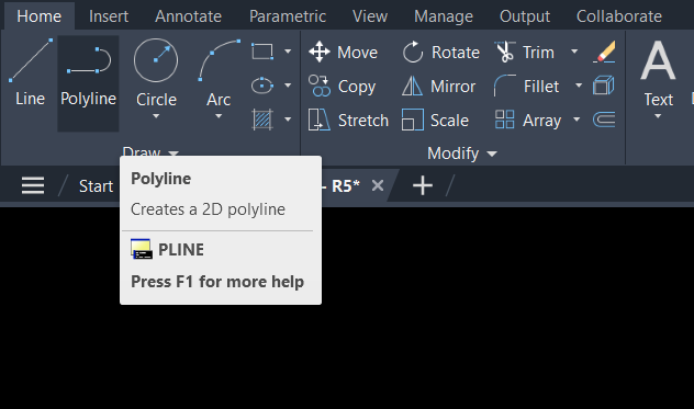
POLYLINE (PL)
The POLYLINE command creates a connected sequence of line segments or arcs. Unlike individual lines, a polyline is treated as a single object, which makes it easier to manipulate. Polylines are useful for creating complex shapes that require multiple segments to be connected seamlessly.
Basic Editing Commands
MOVE (M)
The MOVE command allows you to move objects from one location to another within your drawing. By selecting the object and specifying a base point and a second point, you can precisely place objects where you need them.
COPY (CO or CP)
The COPY command duplicates selected objects and places the copies in a specified location. This command is particularly useful when you need to create multiple instances of an object, such as repeating patterns or components.
ROTATE (RO)
The ROTATE command allows you to rotate objects around a specified base point. You can specify the angle of rotation, which can be useful for positioning objects at precise angles, such as tilting a part of your design.
SCALE (SC)
The SCALE command adjusts the size of objects. By specifying a base point and a scale factor, you can make objects larger or smaller while maintaining their proportions. This command is essential when resizing elements to fit within a specific design.
TRIM (TR)
The TRIM command is used to remove portions of objects that extend beyond or intersect with other objects. This command is particularly useful for cleaning up your drawing, such as cutting off parts of a line that extend past a boundary.
EXTEND (EX)
The EXTEND command is the opposite of TRIM. It extends the length of an object to meet the edge of another object. This command is useful when you need to lengthen lines or shapes to fit within a specific area.
OFFSET (O)
The OFFSET command creates a parallel copy of an object at a specified distance. This is useful for creating parallel lines, concentric circles, or similar shapes that maintain a consistent distance from the original object.
Advanced Drawing and Editing Commands
HATCH (H)
The HATCH command fills an enclosed area with a pattern, solid color, or gradient. Hatching is often used to represent different materials or to emphasize specific areas of a drawing. You can customize the hatch pattern to suit your design requirements.
MIRROR (MI)
The MIRROR command creates a mirrored copy of an object across a specified axis. This command is useful for creating symmetrical designs, such as mirrored components in architectural or mechanical drawings.
ARRAY (AR)
The ARRAY command creates multiple copies of an object arranged in a specified pattern, such as a rectangular grid or circular pattern. This command is ideal for creating repetitive elements, like rows of seats or bolts in a circular pattern.
FILLET (F)
The FILLET command creates a rounded corner between two lines or arcs by specifying a radius. This command is useful for smoothing out sharp corners and giving your design a more polished appearance.
CHAMFER (CHA)
The CHAMFER command creates a beveled edge between two lines by specifying a distance along each line. This command is often used in mechanical design to create chamfered edges on parts.
3D Modeling Commands
EXTRUDE (EXT)
The EXTRUDE command creates a 3D object by extending a 2D shape along a specified path. This command is fundamental for turning flat shapes into three-dimensional models, such as creating walls from a floor plan.
REVOLVE (REV)
The REVOLVE command creates a 3D object by rotating a 2D shape around an axis. This is particularly useful for creating objects with rotational symmetry, such as vases or wheels.
UNION (UNI)
The UNION command combines two or more 3D objects into a single object. This command is useful for merging components into a single, cohesive model.
SUBTRACT (SU)
The SUBTRACT command removes one 3D object from another, creating a cutout or hole. This command is essential for operations like creating windows in a wall or subtracting a shape from another to achieve a desired form.
INTERSECT (IN)
The INTERSECT command creates a new 3D object from the overlapping volume of two or more objects. This is useful when you need to find the common area between multiple objects in a design.
Working with Text and Dimensions
TEXT (T)
The TEXT command allows you to add single-line text annotations to your drawing. You can specify the text size, style, and location, making it easy to label parts of your design.
MTEXT (MT)
The MTEXT command creates multi-line text blocks with more formatting options than the TEXT command. This command is useful for adding paragraphs or detailed notes to your drawings.
DIMENSION (D or DIM)
The DIMENSION command automatically creates dimensions based on the selected objects. You can create linear, aligned, angular, radial, and other types of dimensions, making it easy to add precise measurements to your drawings.
LEADER (LE)
The LEADER command creates a leader line with an annotation at the end, typically used to point out or label specific parts of a drawing. This command is particularly useful for adding notes or callouts.
LAYOUT and ORGANIZATION Commands
LAYER (LA)
The LAYER command manages the layers in your drawing. Layers allow you to organize different elements of your drawing into categories, which can be toggled on or off for better clarity and control.
BLOCK (B)
The BLOCK command allows you to create a block—a collection of objects that can be treated as a single entity. Blocks are reusable elements that can be inserted into other drawings, saving time and ensuring consistency.
WBLOCK (WB)
The WBLOCK command, or “Write Block,” creates a block that is saved as a separate file. This allows you to reuse the block in other drawings or share it with others, enhancing collaboration.
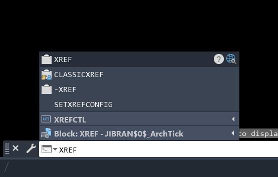
XREF (XR)
The XREF command attaches external reference files to your drawing. This is useful for working on large projects where multiple drawings need to be coordinated, such as architectural plans.
PLOT (P)
The PLOT command is used to print or plot your drawing. You can specify the scale, paper size, and layout to ensure your drawing is accurately represented on paper or as a PDF.
Suggested Read- AutoCAD for Beginners
Conclusion
AutoCAD commands are the backbone of your design workflow, enabling you to create, edit, and organize your drawings with precision and efficiency. By mastering these essential commands, you can significantly improve your productivity and take full advantage of AutoCAD’s powerful features. Whether you’re a beginner just starting out or an experienced user looking to refine your skills, understanding how to use these commands effectively is key to achieving success in your design projects.
FAQs
What is the most commonly used AutoCAD command?
The LINE command is one of the most commonly used commands in AutoCAD, as it is fundamental to creating most designs. However, commands like MOVE, COPY, and TRIM are also frequently used in everyday drafting tasks.
How can I speed up my work in AutoCAD?
Learning keyboard shortcuts for common commands and customizing your workspace can significantly speed up your work in AutoCAD. Additionally, mastering commands like ARRAY and OFFSET can automate repetitive tasks, saving time.
What is the difference between the LINE and POLYLINE commands?
The LINE command creates individual line segments, each treated as a separate object. The POLYLINE command creates a sequence of connected line segments that are treated as a single object, making it easier to manipulate the entire shape.
Can I customize AutoCAD commands?
Yes, AutoCAD allows users to customize commands using the CUI (Customize User Interface) editor. You can create custom macros, change keyboard shortcuts, and modify toolbars to better suit your workflow.
What is the purpose of the LAYER command in AutoCAD?
The LAYER command helps you organize your drawing by assigning different elements to specific layers. Layers allow you to control the visibility, color, and line type of different parts of your drawing, making it easier to manage complex designs.
How do I create 3D models in AutoCAD?
Creating 3D models in AutoCAD typically involves commands like EXTRUDE, REVOLVE, and UNION. These commands allow you to build three-dimensional shapes from 2D drawings, which can then be further edited and refined.